- Catalogs
- JENOPTIK AG
- Modulators
Modulators
1 /14Pages

Modulators
1 /14Pages
Catalog excerpts

Amplitude Modulator ALM Electro-optical light modulator based on liquid crystals With the help of the ALM the light intensity or the polarization state can be modulated without mechanical moving parts. By applying a control voltage to a twisted nematic liquid crystal layer the polarization state of passing light is altered. By mounting the ALM between two polarizers or with a single polarizer at the light output (if polarized light is used!), a tunable amplitude attenuation of the light throughput can be achieved. Optoelectronic Systems
Open the catalog to page 1
Amplitude Modulator ALM Electro-optical light modulator based on liquid crystals Specifications Wavelength range Contrast (monochromatic) Transmission (without polarizers) Switching time (valid for crossed polarizers) Driving frequency Active area, diameter Optional: • Mounted with film polarizers (for VIS range) or AR coating • Other apertures on request • For 730 nm – 1600 nm only available without polarizers Transmission – Voltage - Characteristic Transmission – Time – Dependence JENOPTIK I Healthcare & Industry Healthcare Business Unit JENOPTIK Optical Systems GmbH Goeschwitzer Strasse 25...
Open the catalog to page 2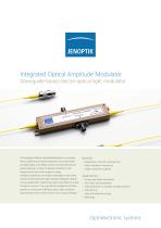
Integrated Optical Amplitude Modulator Waveguide-based electro-optical light modulator The Integrated Optical Amplitude Modulator is a compact fiber-coupled electro-optical modulator that works based on MgO:LiNbO3 and LiNbO3 crystals. Providing fast electrooptical response, it allows amplitude modulation with frequencies as high as the Gigahertz range. Available modulators can handle wavelengths in the visible and the infrared spectral range. Standard-designed modulators use polarization maintaining single mode fibers to couple the light in and out. They may also be configured with fiber systems...
Open the catalog to page 3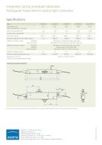
Integrated Optical Amplitude Modulator Waveguide-based electro-optical light modulator Specifications Type Wavelength [nm] Other wavelengths on request Insertion Loss, typical [dB] Extinction, typical Minimum optical rise time 10/90, typical Optical connection, input Standard Fiber connector Polarisation maintaining single mode fiber Bare fiber, FC/PC connector or FC/APC connector Optical connection, output Standard Optional Fiber connector Polarisation maintaining single mode fiber Single mode or multi mode fiber Bare fiber, FC/PC or FC/APC connector Half wave voltage, typical Maximum optical...
Open the catalog to page 4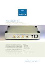
Pulse Selector IOM Pulse Driver / Pulse Picker Controller for Integrated-Optical Amplitude Modulators The Pulse Selector IOM is a pulse picker controller for a reliable reduction of high pulse laser repetition rates. It can • Short rise times be used as triggered pulse generator for modulator driving • High extinction too. The preferred modulator type is JENOPTIK AMXXXXb. • High repetition rate • Automatic bias-control For normal operation, the Pulse Selector IOM requires only the synchronizing signal of the laser source. It is controlled by PC via the USB port using a command set. • Reduction...
Open the catalog to page 5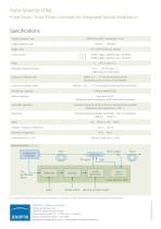
Pulse Selector IOM Pulse Driver / Pulse Picker Controller for Integrated-Optical Modulators Specifications Usable modulator type AMXXXXb (XXXX: wavelength in nm) Trigger repetition rate Trigger input TTL / LVTTL (50 Ohms), SMA(f) Division factor 2, 3, 4, … 16383 (Trigger repetition rate < 50 MHz) 3, 4, 5, … 16383 (Trigger repetition rate > 50 MHz) Modulator opening window 10 ns … 255 ns, step 1 ns single pulses or pulse bursts SMA(f), 0 V … 7 V (connected to 50 Ohms) Monitoring output at the rear side (SMA(f)) Output to modulator (bias) SMC(m), - 10 V … 10 V (connected to high-resistance connector)...
Open the catalog to page 6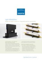
Light Modulators based on liquid crystals or integrated-optical waveguides Light Modulation in the Visible and Near-Infrared Spectral Range The light modulators developed and manufactured by Jenoptik are utilized for modulation of amplitude, phase, polarization and spectrum as well as for pulse shaping, pulse rate reduction and fast switching of light from laser sources of diverse powers. The modulators based on on liquid crystal cells or fibercoupled integrated optics are characterized by short switching times and a wide operating wavelength range in the visible (VIS) and near-infrared (NIR)...
Open the catalog to page 7
Light Modulators based on liquid crystals or integrated-optical waveguides Specifications glass substrate transparent electrode alignment layer polarized light wavefront Phase modulation with liquid crystals Schematic layout of an integrated-optical amplitude modulator Liquid Crystal Spatial Light Modulators Fiber-Coupled Integrated-Optical Modulators The liquid crystal spatial light modulators SLM-S modulate light in the The integrated-optical modulators are compact fiber-coupled, wavelength range from 430 nm to 1600 nm and are particularly suited electro-optical modulators based on Lithium...
Open the catalog to page 8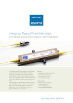
Integrated Optical Phase Modulator Waveguide-based electro-optical light modulator The Integrated Optical Phase Modulator is a compact fibercoupled electro-optical modulator that works based on MgO:LiNbO3 and LiNbO3 crystals. Providing fast electrooptical response, it allows phase modulation with frequencies as high as the Gigahertz range. Available modulators can handle wavelengths in the visible and the infrared spectral range. Standard-designed modulators use polarization maintaining single mode fibers to couple the light in and out. They may also be configured with fiber systems or connectors...
Open the catalog to page 9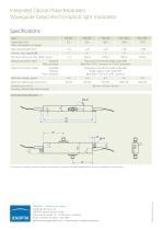
Integrated Optical Phase Modulator Waveguide-based electro-optical light modulator Specifications Type Wavelength [nm] Other wavelengths on request Insertion Loss, typical [dB] Minimum optical rise time 10/90, typical Optical connection, input Standard Fiber connector Polarisation maintaining single mode fiber Bare fiber, FC/PC connector or FC/APC connector Optical connection, output Standard Optional Fiber connector Polarisation maintaining single mode fiber Single mode or multi mode fiber Bare fiber, FC/PC or FC/APC connector Half wave voltage, typical Maximum optical input power (cw) Dimensions...
Open the catalog to page 10All JENOPTIK AG catalogs and technical brochures
 Optoelectronic modules
2 Pages
 PROGRES® C14plus
2 Pages
 PROGRES SpeedXT core® 5
2 Pages
 ELM-650-992-7
9 Pages
 ELEM-DP 10k
2 Pages
 ELEM 10k
2 Pages
 JenLas® fiber ns 25 – 105
2 Pages
 Fiber Lasers
2 Pages
 Lasers for Micro Machining
4 Pages
 Coating of Polymer Optics
2 Pages
 Optical Components
2 Pages
 Lighting Solutions
18 Pages
 Single Emitters & Bars
80 Pages
 Diode Laser Modules
36 Pages
 Diode Laser Stacks
44 Pages
 Diode-Pumped Thin-Disk Lasers
16 Pages
 Lasers for Medicine
6 Pages


- AMOT cutting machine
- AMOT digital camera
- Visible imager
- AMOT laser cutting machine
- AMOT cutting machine for industrial applications
- AMOT CMOS camera
- AMOT industrial camera
- LED lighting
- AMOT high-precision cutting machine
- AMOT infrared camera
- AMOT process software
- Monitoring camera system
- Full-color camera system
- Computer-aided design software
- AMOT high-speed cutting machine
- AMOT plastic cutting machine
- Fiber laser cutting machine
- AMOT USB camera
- Design software solution
- Image processing camera module