- Catalogs
- JENOPTIK AG
- ELM-650-992-7
ELM-650-992-7
1 /9Pages

ELM-650-992-7
1 /9Pages
Catalog excerpts
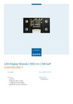
LED Display Module | 650 nm | AlInGaP ELM-650-992-7 Prototype Pat. US 8847241 B2 Features Applications - Radiation 650 nm (red) - 7-segment chip (5-times) - Optimized to avoid reflections
Open the catalog to page 1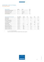
Maximum Ratings1 Forward current (DC) per segment Operating temperature range Storage temperature range Junction temperature Symbol Value Unit Optical and Electrical Characteristics1 Forward voltage Reverse voltage Luminous intensity/segment Iv ratio segment to segment Iv ratio to adjacent chip Peak wavelength Centroid wavelength Spectral bandwidth at 50% Temperature coefficient of Vf Temperature coefficient of Iv Temperature coefficient of 1c Test conditions Symbol Min Tamb = 25°C, unless otherwise specified measured on bare chip on TO-18 header with JENOPTIK Polymer Systems equipment
Open the catalog to page 2
ELM-650-992-7 | 650 nm | Prototype Typical Characteristics Segment of 7-Segment Chip Forward Voltage vs. Forward Current (typical) Luminous Intensity vs. Forward Current (typical) 30 Current Reduction Spectral Power Distribution (typical) Ambient Temperature vs. Maximal Forward Current Intensity [normalised]
Open the catalog to page 3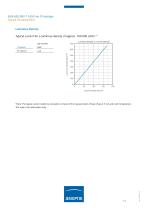
ELM-650-992-7 | 650 nm | Prototype Typical Characteristics Luminous Density Typical current for a luminous density of approx. 100 000 cd/m² * Luminous Density vs. Current Density Typ. Current [mA] Luminous Density [cd/cm²] Current Density [A/cm²] *Note: The typical current results by calculation on basis of the measurements of bare chips at 5 mA and room temperature. This value is for information only.
Open the catalog to page 4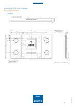
ELM-650-992-7 | 650 nm | Prototype Mechanical Dimensions Module Molex 51281-1494(14 pins)
Open the catalog to page 5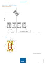
ELM-650-992-7 | 650 nm | Prototype Mechanical Dimensions
Open the catalog to page 6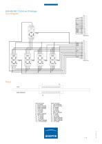
ELM-650-992-7 | 650 nm | Prototype Circuit Diagram Pinout 1 14 front connector 1 -"b" anode 2 - Chip E cathode 3 - Chip B cathode 4 - Chip A cathode 5 -"g" anode 6 -"a" anode 7 - "f" anode 8 - Chip C cathode 9 - "dp" anode 10 - "c" anode 11 - "d" anode 12 - "e"anode 13 - Chip D cathode 14 - not connected back connector 1 - not connected 2 - Chip D cathode 3 - "e" anode 4 - "d" anode 5 - "c" anode 6 - "dp" anode 7 - Chip C cathode 8 - "f" anode 9 - "a" anode 10 - "g" anode 11 - Chip A cathode 12 - Chip B cathode 13 - Chip E cathode 14 - "b" anode
Open the catalog to page 7
Labeling Manufacturer Type_ Order N° Quantity Charge Purchase Order N° Patent JENOPTIK Polymer System GmbH ELM-650-992-7_ 26.06.201S JENOPTIK Polymer System GmbH Manufactu rei ELM-6S0-992-7 626937 Type 100 pcs 1234567 1234567S90 K ope nicker Sir. 325, Hausim, 12555 Berlin TelJFax: +43' 30 S57G-2543 / -2545
Open the catalog to page 8
ELM-650-992-7 | 650 nm | Prototype General Information Handling Die surface and contact wires are very sensitive to mechanical stress. Lift and assemble the module carefully. We accept no liability for errors during handling and resulting damage. Modules have to be handled ESD sensitive. Safety Advice* The evaluation of eye safety occurs according to the standard CIE/IEC 62471:2006 (“Photobiological Safety of Lamps and Lamp Systems”). Within the risk grouping system of this CIE standard the LED module in this data sheet is assigned into the Group 1 – Low Risk. JENOPTIK Polymer Systems GmbH Köpenicker...
Open the catalog to page 9All JENOPTIK AG catalogs and technical brochures
 Optoelectronic modules
2 Pages
 PROGRES® C14plus
2 Pages
 PROGRES SpeedXT core® 5
2 Pages
 ELEM-DP 10k
2 Pages
 ELEM 10k
2 Pages
 JenLas® fiber ns 25 – 105
2 Pages
 Fiber Lasers
2 Pages
 Lasers for Micro Machining
4 Pages
 Coating of Polymer Optics
2 Pages
 Optical Components
2 Pages
 Modulators
14 Pages
 Lighting Solutions
18 Pages
 Single Emitters & Bars
80 Pages
 Diode Laser Modules
36 Pages
 Diode Laser Stacks
44 Pages
 Diode-Pumped Thin-Disk Lasers
16 Pages
 Lasers for Medicine
6 Pages


- AMOT cutting machine
- AMOT digital camera
- Visible imager
- AMOT laser cutting machine
- AMOT cutting machine for industrial applications
- AMOT CMOS camera
- AMOT industrial camera
- LED lighting
- AMOT high-precision cutting machine
- AMOT infrared camera
- AMOT process software
- Monitoring camera system
- Full-color camera system
- Computer-aided design software
- AMOT high-speed cutting machine
- AMOT plastic cutting machine
- Fiber laser cutting machine
- AMOT USB camera
- Design software solution
- Image processing camera module