
- Catalogs
- jbj Techniques Limited
- Shaft locking devices


- Company
- Products
- Catalogs
- News & Trends
- Exhibitions
Shaft locking devices

Shaft locking devices
SIT-LOCK keyless locking devices are designed for superior shaft-hub connections without traditional keyed systems. They offer easy assembly and disassembly, superior holding power, and precision location, suitable for various industrial applications like cams and timing devices.
SIT-LOCK devices operate within -20°C to 150°C, available in 10 types for versatile use. They handle torque and axial forces with a recommended friction coefficient of 0.12 for lubricated installations. Ensuring transmissible torque exceeds operational torque is crucial to prevent slippage.
Consider startup torque, which can be up to four times the nominal torque. Devices use h8/H8 or h11/H11 tolerances. Installation involves tightening screws to specified torque, and removal requires even loosening.
SIT-LOCK devices increase shaft strength, ease installation and removal, and handle simultaneous loads without requiring shaft slots, maintaining strength and reducing costs.
They are not friction couplings; excessive slip can cause damage. Avoid lubricants like molybdenum disulfide. Consult the technical office for applications outside the temperature range.
- Transmit torque and tolerate axial forces simultaneously.
- Formulas for calculating transmissible torque and minimum hub diameter.
- Suitable for continuous alternating loads with no backlash.
- Tighten screws to specified torque for proper transmission.
- Consider temperature influences for applications from -20°C to +200°C.
- Avoid molybdenum disulphide-based lubricants.
- Use matching thermal expansion coefficients for high-temperature applications.
- Tables provide torque, axial force, and pressure values.
- Data includes elastic limits of hub materials and pressure factors.
- Self-centering devices suitable for high radial loads.
- Installation involves cleaning surfaces, applying oil, and tightening screws in a criss-cross sequence.
- Removal involves loosening screws and using removal threads.
Includes dimensions, clamping screw specifications, and performance data like transmissible torque and axial force.
For further information, contact jbj Techniques Limited.
Catalog excerpts
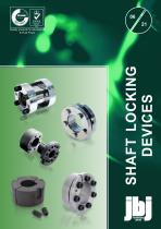
SHAFT LOCKING DEVICES
Open the catalog to page 1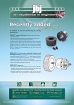
Recently added . . . pages 76 to 82 In addition to the SIT-LOCK® keyless locking elements the . . . SER-SIT® taper lock bush designed to give the following: » perfect assembly. » rapid dismounting of the pulley and other transmission equipment. » no special tools requirement except hexagonal key. The large range of available finished bores ensures that an immediate assembly can be made thus avoiding costly factory downtime. Fastening by SER-SIT® bushes allows the removal of any clearance between hub and bore so that fretting corrosion is positively eliminated. SER-SIT® bushes are interchangeable...
Open the catalog to page 2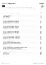
Page SIT-LOCK® Keyless Locking Elements (advantages) . . . . . . . . . . . . . . . . . . . . . . . . . . . . . . . . . . . . . . . . . . . . . . . . . . Features - internal. . . . . . . . . . . . . . . . . . . . . . . . . . . . . . . . . . . . . . . . . . . . . . . . . . . . . . . . . . . . . . . . . . . . . . . . . . . . . . Application examples . . . . . . . . . . . . . . . . . . . . . . . . . . . . . . . . . . . . . . . . . . . . . . . . . . . . . . . . . . . . . . . . . . . . . . . . . . . SIT-LOCK 3 Internal locking device - self-centring . . . . . . . . . . . . . . . . . . . . . . . . ....
Open the catalog to page 3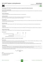
SIT-LOCK® Keyless Locking Elements Advantages compared to conventional systems Advantages of SIT-LOCK® on the shaft-hub connection compared with traditional systems Easy assembly and disassembly Both actions take place by locking and unlocking the clamping screws with common tools. The use of a torque wrench is only necessary when a more precise torque is required. Superior holding power The action of the clamping cones creates shaft clamping torque superior to a normal keyed hub. Overload protection When the pre-set torque is exceeded SIT-LOCK® will slip, preventing the connected elements from...
Open the catalog to page 5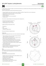
SIT-LOCK® Keyless Locking Elements Advantages compared to conventional systems A shaft to hub lock is critical in the design of a mechanical transmission as an unsuitable choice could cause serious damage to the machine or system and result in economic loss. Shaft-hub coupling designs must take several parameters into account: Assessing application loads: torque, bending moment, axial force, radial force. Stresses that may occur simultaneously; Alternating loads, sudden starts and stops, very rapid acceleration; Fatigue limits of the coupling components; Suitable material use; Frequent installation...
Open the catalog to page 6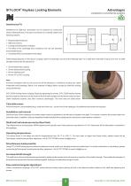
SIT-LOCK® Keyless Locking Elements Advantages compared to conventional systems Requires tight tolerances. Difficult to remove. Locking area temperature changes. The effect of the centrifugal force created by the hub can decrease transmissible torque. » Increased stress concentrated on the edges. Interference fit shaft-hub connections can be achieved by cooling the shaft or heating the hub. This type of connection is not widely used for the following reasons: Shaft strength depends on the type of coupling used As an example, we look at the following data. For a shaft with a diameter d equal to 50...
Open the catalog to page 7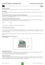
SIT-LOCK® Keyless Locking Elements Oxidation protection Even in damp environments, the pressures created along the contact surfaces do not allow for oxidation, ensuring easy removal of the locked parts. No backlash Connection in transmissions using SIT-LOCK® locking devices are perfectly rigid and there is no backlash that could impair motion transmission or machine precision over time. Recommended for applications subject to continuous alternating loads By using SIT-LOCK® locking devices, the stresses generated by alternating or sudden loads are distributed over the entire surface of the shaft...
Open the catalog to page 8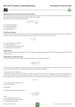
SIT-LOCK® Keyless Locking Elements Applications with simultaneous torque and axial force SIT-LOCK® locking devices can simultaneously transmit torque Mt and tolerate an axial force Fax. The table shows the maximum permissible values. Where both values are present simultaneously, the transmissible torque Mt value decreases. Below is the formula for calculating transmissible torque: Mtam = Mtam = permissible torque (Nm) Mt = torque stated in table (Nm) FAXR = required axial force (N) d = shaft diameter (mm) Radial force influence The radial force FR affects the contact pressure on the shaft and hub...
Open the catalog to page 9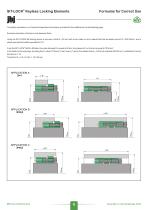
SIT-LOCK® Keyless Locking Elements To simplify calculations, our Technical Department has drawn up a table for the coefficient K on the following page. Example calculation of minimum hub diameter Dmin Using the SIT-LOCK® 5B locking device to connect a shaft d = 50 mm with a hub made out of a material that has an elastic load σ0,2 = 500 N/mm², and a shape type and hub width equivalent to X=1. From the SIT-LOCK® 5B 50 x 80 table, the outer diameter D is equal to 80 mm, the pressure Pn on the hub is equal to 70 N/mm². In the table on the next page, by taking the Pn value (70 N/mm²), the X value (1)...
Open the catalog to page 10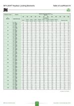
SIT-LOCK® Keyless Locking Elements Elastic load of hub material σ0,2 [N/mm²] Application type continued overleaf . . .
Open the catalog to page 11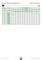
SIT-LOCK® Keyless Locking Elements Elastic load of hub material σ0,2 [N/mm²] Application type
Open the catalog to page 12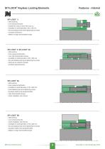
SIT-LOCK® Keyless Locking Elements Features - internal SIT-LOCK® 3 » Self-centering. » Low surface pressures. » Suitable for using on hubs with a low σ0.2. » Available for shaft diameters of 6 to 130 mm. » No axial displacement when tightening the screws. » Compact dimensions. » Medium to high transmissible torques. SIT-LOCK® 4, SIT-LOCK® 4A » Self-centring. » Even pressure distribution. » Very high transmissible torques. » Available for shaft diameters of 25 to 400 mm. » No axial displacement when tightening the screws. » Removal via extraction threads. » Excellent perpendicularity. SIT-LOCK®...
Open the catalog to page 13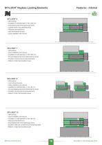
SIT-LOCK® Keyless Locking Elements Features - internal SIT-LOCK® 6 » Self-centring. » Available for shaft diameters of 18 to 200 mm. » Axial displacement when tightening screws. » Optimal shaft-to-hub perpendicularity. » Reduced axial dimensions. » High transmissible torques. » Quick installation and removal. SIT-LOCK® 7 » Self-centring. » Quick installation and removal. » Available for shaft diameters of 18 to 200 mm. » No axial displacement when tightening the screws. » Excellent concentricity and perpendicularity. » Medium to high transmissible torques. SIT-LOCK® 8 » Self-centring. » Low surface...
Open the catalog to page 14All Jbj Techniques Limited catalogs and technical brochures
 PUMP DRIVE COMPONENTS
61 Pages
 HIGH/LOW, 2 STAGE / GEAR PUMPS
14 Pages
 S-Flex Couplings
32 Pages
 Hydraulic Gear Motors
56 Pages
 Planetary Gearboxes
48 Pages
 Yoke Drive Flywheel Couplings
14 Pages
 Bearing Supported Stub Shafts
12 Pages
 This is what we do
1 Page
 HQ series vane pumps
48 Pages
 Pneumatic Starters
6 Pages
 Coolers & Heat Exchangers
78 Pages
 Hydraulic power take-off units
28 Pages
 Gear pump summary
12 Pages
 FLUID POWER ACCESSORIES
66 Pages
 F15 Ferra Series
20 Pages
 KT Pressure Switch
8 Pages
 Rotary Gear Flow Dividers
16 Pages
 W Series
8 Pages
 GPA Series
18 Pages
 jbj Coolers Summary
2 Pages
 PIPE FLANGES PORT FLANGES
102 Pages
 TANKS / RESERVOIRS
22 Pages
 PRESSURE INTENSIFIERS
22 Pages
 SCREW PUMPS
50 Pages
 HAZARDOUS AREAS SCREW PUMPS
24 Pages
 SCREW PUMP RELIEF VALVES
14 Pages
 BV Series VANE PUMPS
94 Pages
 BQ Series VANE PUMPS
108 Pages
 TQ and TV Series VANE PUMPS
36 Pages
 HQ Series VANE PUMPS
38 Pages
 B1 and B2 Series VANE PUMPS
10 Pages
 All steel gear couplings
26 Pages
 This is jbj Techniques!
28 Pages
 Vane pumps
10 Pages
 Fluid power accessories
54 Pages
 Fluid reservoirs
22 Pages
 pressure intensifiers
22 Pages
 screw pumps
50 Pages
 API 676 compliant screw pumps
24 Pages
 Petrol engine adaptors
6 Pages
 Torque limiting couplings
20 Pages
 Torsional couplings
48 Pages
 jbj PRODUCT SUMMARY
6 Pages
 Equipment for Hazardous Areas
44 Pages
 PDC
PDC58 Pages


- Pump
- Industrial pump
- Centrifugal pump
- Vessel
- Liquid filter
- Electric gearmotor
- Planetary gearbox
- Coaxial gearhead
- Hydraulic pump
- Metal tank
- Right angle gearhead
- Solid-shaft gearhead
- Flexible coupling
- Shaft shaft coupling
- Hollow-shaft gearhead
- Gear train gear reducer
- Gearbox for industrial applications
- Friction brake
- Transmission gearhead
- Multi-stage gearhead