- Catalogs
- JAKOB Antriebstechnik GmbH
- Datasheet SC
- Company
- Products
- Catalogs
- News & Trends
- Exhibitions
Datasheet SC
1 /2Pages

Datasheet SC
1 /2Pages
Catalog excerpts

Clamping Elements Mechanical Power Clamping Screw I Series SC • wedge mechanism as force amplifier • high clamping forces • maximum operational safety • low actuation torque • simple & manual operation The power clamping screws of the SC series are equipped with a wedge system as force amplifier. This innovative system allows for highest clamping forces with low actuation torques and simple manual operation. The robust design of all parts, the self-locking mechanism as well as a high overload capability guarantee maximum operational safety. The clamping screws of the SC series have various application possibilities, mainly in presses, punches and machine tools, as well as in jigs, fixtures and similar devices. Function: The wedge clamping system of the SC clamping screw is self-locking in each clamping position due to its geometry and offers a clamping stroke of up to 3 mm. This way, depending on the actuation torque, very high clamping forces up to the nominal clamping force can be achieved. Clamping procedure: The infeed of the clamping screw down to a solid contact with the part to be clamped (7) is the first step, done by manually turning the housing (1) clockwise. Only then, the hexagon of the actuation spindle (2) should be turned clockwise, thus moving the forced-in key (3) in axial direction and pressing the wedge parts (4) in radial direction. The latter motion results in the axial stroke of the thrust piece (5) against the workpiece (7). The clamping force is led over the wedge bearing (6) through the housing (1) into the clamping device (8). After approximately two turns of the actuation hexagon the travel of the thrust piece will be blocked by an internal fixed stop and the torque wrench will disengage although the required clamping force has not been generated; the clamping operation has to be repeated. The clamping stroke state is indicated by the operating path “s”. The maximum clamping position is reached when the lower cylindrical portion of the actuation hexagon is even with the top of the housing (Fig. A2). Release: The release procedure is carried out in reverse order. By turning the operating hexagon to the left up to the fixed back stop (Fig. A1), the wedge slide moves back and the clamping mechanism is released. Coil springs push the pressure piece and the wedges back into the starting position.
Open the catalog to page 1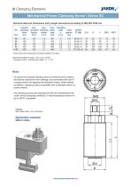
Technical data and dimensions [mm]: length dimensions according to DIN ISO 2768 mH *further sizes and threads (inch thread) available on request allowed temperature range: -40°C up to +250°C **hexagon socket - operating pin length: s = 17 mm Note: • to ensure the required clamping force is achieved and to protect the internal mechanism from damage, we recommend the use of a torque wrench for applying the actuation torque. Under certain conditions, clamping is also acceptable with a standard wrench or socket wrench. • the clamping screws are lubricated for life and maintenance free under normal...
Open the catalog to page 2All JAKOB Antriebstechnik GmbH catalogs and technical brochures
 Datasheet HMD
1 Page
 Datasheet ZDF-o
1 Page
 Datasheet ZDF-u
1 Page
 Datasheet KHS
1 Page
 catalogue servo- couplings
56 Pages
 Datasheet MOH-C
1 Page
 Datasheet MJT & MJT-C
1 Page
 Datasheet MJT
1 Page
 Datasheet SKB-EK
1 Page
 Datasheet MSP / MSPD
1 Page
 Datasheet MKA
1 Page
 Datasheet MOH
1 Page
 Datasheet SKY-ES
1 Page
 Datasheet SKY-KS
1 Page
 datasheet SKW
1 Page
 Datasheet SKW-EK
1 Page
 MCF-VA
2 Pages
 Datasheet WD-VA
1 Page
 Datasheet SKY-KP
1 Page
 Datasheet SKW-KP
1 Page
 Datasheet WDS
1 Page
 Datasheet MKM
1 Page
 Datasheet MKP
1 Page
 Datasheet SKB
1 Page
 Datenblatt MKG-VA
1 Page
 Datasheet EKHZ
1 Page
 Datasheet Simple-Flex
2 Pages
 Datasheet MCG
1 Page
 Datasheet EKM-VA
1 Page
 Distanzkupplung WDB
1 Page
 Datasheet SKB-KP
1 Page
 Datasheet SKR
1 Page
 Datasheet KG
1 Page
 Datasheet KG-VA
1 Page
 Datasheet KP
1 Page
 Datasheet KM
1 Page
 Datasheet KR
1 Page
 Datasheet KSS
1 Page
 Datasheet MKG
1 Page
 Datasheet KGH
1 Page
 Datasheet KSD
1 Page
 Datasheet KPS
1 Page
 Datasheet KE
1 Page
 Datasheet KPP
1 Page
 Datasheet KGH-VA
1 Page
 Datasheet ESM-A
1 Page
 Datasheet EKH
1 Page
 Datasheet EKM
1 Page
 Datasheet KXL
2 Pages
 Datasheet MDA
1 Page
 Datasheet EKS
1 Page
 Datasheet KGE
1 Page
 Datasheet MCA-S / MCA-T
1 Page
 Datasheet MCA
1 Page
 Catalogue Clamping Elements
26 Pages
 Catalogue Safety Couplings
24 Pages
 Datasheet MDR
1 Page
 Metal Bellows Couplings
2 Pages
 Hydraulic load cells
2 Pages


- Force sensor
- Nut
- Flexible coupling
- Shaft shaft coupling
- Metal nut
- Flange coupling
- Analog load cell
- Torque coupling
- Transmission coupling
- Zero-backlash shaft coupling
- Hexagonal nut
- Stainless steel nut
- Compact coupling
- Clamping element
- Misalignment correction coupling
- Overload clutch
- Hydraulic clamping
- Industrial coupling
- Maintenance-free coupling