
- Catalogs
- JACQUES DUBOIS
- catalogue

catalogue

catalogue
Electromagnetic Compatibility (EMC) is crucial for ensuring that equipment operates without interference in its electromagnetic environment. Since 1996, it has been a legal requirement in Europe and many industrialized countries. Ignoring EMC can lead to minor nuisances or severe service interruptions.
EMC is vital for preventing issues ranging from minor interference on radios and TVs to severe industrial process failures or unintended device activations. It also helps prevent electronic eavesdropping and ensures system safety and functionality.
EMC ensures that equipment neither emits nor is susceptible to electromagnetic disturbances. Standard limits manage emissions and immunity to allow equipment to coexist without interference.
EMI can originate from natural phenomena like lightning or artificial sources such as radio transmitters, digital circuits, and industrial equipment, generating unwanted high-frequency emissions.
Shielding reduces electromagnetic emissions and improves immunity, enhancing electrical continuity and equipotentiality without requiring a perfect Faraday cage.
Shielding effectiveness is measured by the reduction in field strength after applying the shield, depending on material and thickness.
Electromagnetic shielding protects electronic equipment from external EMI using conductive or magnetic barriers. Shielding Efficiency (SE) is the ratio of the electromagnetic field without the shield to the field with the shield installed.
Measured in decibels (dB), SE is calculated using SE (dB) = 20 Log (Ei/Es), where Ei is the incident field and Es is the transmitted field. Effectiveness combines reflection loss and absorption loss.
Common shielding materials include copper, aluminum, ordinary steel, and monel, each with specific conductivity and permeability properties. Skin depth affects absorption loss and depends on these properties and the electromagnetic wave frequency.
Openings, slots, and seams can reduce shielding effectiveness, especially at higher frequencies. Conductive gaskets and sealing methods help maintain shielding integrity.
Shield performance depends on frequency range and whether the concern is susceptibility or emissions. Different environments have varying requirements for field immunity and emission limits.
Shielding effectiveness is limited by the largest openings in the enclosure, so ensuring continuity at these points is crucial. Shielding materials and methods must exceed expected requirements for adequate protection.
Discusses materials used in sheet gaskets, including aluminum, monel, and conductive particles. Elastomers include polychloroprene, butadiene nitrile acrylic, ethylene propylene diene, silicone, fluoro silicone, and polyurethane.
Sheet gaskets like TRIMAS, ELASIL, and NEOSIL F can be installed directly on their support. For thicknesses over 3 mm, braces are recommended to limit clamping to 10-15%.
Some gaskets come with double-sided adhesive tapes for easy installation. The temperature of the support and adhesive should be similar, and the gasket should be fixed in one operation, remaining unused for at least 24 hours for adhesive curing.
Explains IP protection levels, with the first number indicating protection against solid materials and the second against liquids.
In humid or industrial environments, consider the potential difference between the shielding element and the metal in contact to prevent corrosion.
Gaskets and grooves are defined by gasket type, seal cross-section, and required watertightness. Installation advice includes ensuring clean, dry surfaces and using appropriate solvents for cleaning.
Contact strips with adhesive surfaces should be used within six months of delivery and stored in original packaging at around 21°C.
Various TRIMET types are described, each with specific installation methods and performance characteristics.
Details the attenuation properties of different metal wires used in TRIMET and the compression forces required for installation.
Outlines specifications for TRIMET and TRISIL IP products, including material composition and performance characteristics.
TRISIL IP ensures IP 68 sealing with specific installation conditions and offers stable mechanical performance across temperatures.
Lists various product references with dimensions and adhesive types.
TISCAT is an elastomer sponge core covered with a metal polyester jacket, featuring a pressure-sensitive adhesive for easy installation.
Made of beryllium copper, plated with tin, nickel, or silver to enhance conductivity and electromagnetic compatibility.
Beryllium copper composition includes 1.8 to 2% beryllium, with cobalt, nickel, and iron making up a maximum of 0.6%, and the remainder being copper.
Provides a guide for determining part numbers based on treatment type, strip shape, and strip type.
NEOSIL F is a silicone material reinforced with Monel wires, offering chemical corrosion and vibration resistance.
- Number of wires per cm²: ≥ 100
- Monel wire diameter: 0.11 mm
- Temperature tolerance: -55 to +200°C
- Hardness: Silicone 40 shore A, Fluoro silicone 60 shore A
- Standard Thicknesses: 0.8 mm ± 0.1, 1.5 to 2.5 mm ± 10%
TISMAT is a sponge elastomer with a conductive coating and adhesive, used for RF shielding.
TRIMAS gaskets are made with metallic mesh for continuous contact and low RF impedance.
Knitted from various metals, these ribbons provide 40 to 80 dB attenuation in electric fields.
Combining a flexible collar with retractable metal mesh, SOMIMAS ensures high-quality earthing and cable support.
Designed for electromagnetic protection in high-interference environments.
- Opening CABSIL: Used for permanent installations, threaded onto cables and heat-shrunk.
- Welded CABSIL: Manufactured with TISCEM for increased attenuation.
- Special CABSIL: Provides specific attenuation levels for different frequencies.
- General Description: Provides transparency and electromagnetic protection.
- Types:
- Flat Glass VUSSIL: Features a metal cloth between acrylic sheets.
- Acrylic VUSSIL: Offers scratch-resistant and anti-reflective surfaces.
- Polycarbonate VUSSIL: Recommended for LCD screens.
- General Description: Designed for electromagnetic protection in ventilation and lighting apertures.
- Types:
- Aluminium SILAIR: Uses honeycomb cells with standard treatments.
- Tin-Plated Steel SILAIR: Offers high efficiency in both constant and impulse fields.
- High-performance panel made with laser-welded square aluminum cells.
- Attenuation levels range from 80 dB at 30 MHz to 120 dB at 1 GHz.
- Designed for electromagnetic shielding of high-speed and HF components.
- Used for creating conductive areas in metal cabinets and enclosures.
- Electromagnetic shielding coatings with nickel, silver-coated copper, or silver particles.
- Available in epoxy and silicone types, suitable for various substrates.
- Copper or aluminum tape for EMI shielding applications.
- Designed to absorb electromagnetic waves in RF cavities.
- Silicone-based thermal interface materials with conductivities from 1.2W/m.K to 14W/m.K.
Catalog excerpts

EMI/RFI Shielding Solutions de and Thermal Management Blindage Électromagnétique et Solutions Management Thermique
Open the catalog to page 1
CONTENTS Introduction / INTRODUCTION : Le blindage eLECTROMAGNeTIQUE / Electromagnetic shielding. . . . . . . . . . . . . . . . . . . . . . . . Les MATeRIAUX / Materials. . . . . . . . . . . . . . . . . . . . . . . . . . . . . . . . . . . . . . . . . . . . . . . . . . . . . . . . . les normes / STANDARDS . . . . . . . . . . . . . . . . . . . . . . . . . . . . . . . . . . . . . . . . . . . . . . . . . . . . . . . . . . LES Couples galvaniques / galvanic potentialS. . . . . . . . . . . . . . . . . . . . . . . . . . . . . . . . . . . . . La mise en œuvre / application. . . . . . . . . . . . . ....
Open the catalog to page 2
ABSORBANTs RF & HYPER / RF & MICROWAVE ABSORBERS : management thermique / thermal management :
Open the catalog to page 3
ELECTROMAGNETIC SHIELDING GENERALITES La Compatibilité ElectroMagnétique (C.E.M.) est l’aptitude d’un équipement à fonctionner dans son environnement électromagnétique sans être perturbé, et sans perturber des équipements voisins ou des services radio-électriques. ElectroMagnetic Compatibility (E.M.C.) is the ability of an equipment to operate in its electromagnetic environment without being disturbed, and without disturbing neighbour equipments or radio services by ElectroMagnetic Interference (E.M.I.). La C.E.M. est une nécessité pour le fonctionnement satisfaisant de tous les systèmes, équipements...
Open the catalog to page 4
ELECTROMAGNETIC SHIELDING Une bonne C.E.M. dicte que chaque équipement ne soit ni perturbateur, ni perturbé. Cette cohabitation implique des précautions pour maîtriser à la fois les émissions électromagnétiques des appareils et leur susceptibilité aux perturbations ambiantes. Comme il n’est pas économiquement et techniquement réaliste de construire des équipements qui n’émettent rien et qui résistent à tout, il existe des règles, sous forme de limites standards, qui permettent de gérer les cohabitations en fonction des principales catégories d’environnement. Ces limites régissent : A sound E.M.C....
Open the catalog to page 5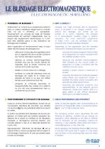
ELECTROMAGNETIC SHIELDING POURQUOI UN BLINDAGE ? Intuitivement, on conçoit qu’un équipement enfermé dans un caisson métallique intégral sans la moindre fuite, ne soit ni émetteur, ni susceptible. Heureusement, ce concept de cage de Faraday quasi-parfaite est rarement indispensable. Pour la plupart des équipements électroniques, la C.E.M. peut être satisfaite grâce à des réalisations de blindage plus modestes. Intuitively, one might conceive that an equipment which is enclosed in an integral metallic vault, without any leakage, will neither be an emitter or a victim. Hopefully, this concept of...
Open the catalog to page 6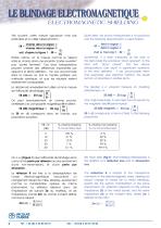
ELECTROMAGNETIC SHIELDING Très souvent, cette mesure rigoureuse n’est pas praticable et on utilise l’approximation : EB = champ dans la région ➀ champ dans la région ➁ Quite often, this formal measurement is not practical and the following approximation is used instead : SE = field in region ➀ field in region ➁ Ei Es Parfois même, on la mesure comme le rapport entre le champ dans une enceinte “portes ouvertes” puis “portes fermées”. Ces deux extrapolations peuvent amener des différences importantes par rapport à la stricte définition : l’on s’en accommode dans la mesure où tout le monde pratique...
Open the catalog to page 7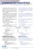
ELECTROMAGNETIC SHIELDING Cette impédance d’onde vaut 377Ω lorsque le blindage se trouve à plusieurs longueurs d’onde λ de la source émettrice. Lorsqu’il est très proche (par exemple à λ/10 ou moins) d’une source essentiellement magnétique, l’impédance du champ Zch est d’autant plus faible et la perte par réflexion est moins bonne (Figure 3). This wave impedance has a value of 377Ω when the shield is at several wavelengths λ from the radiating source. When the shield is very near (like λ/10 or less) from a predominantly magnetic source, the Zw term is correspondingly smaller and the reflection...
Open the catalog to page 8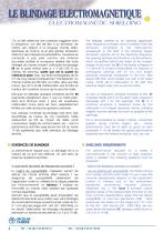
ELECTROMAGNETIC SHIELDING Or, la fuite créée par une ouverture s’aggrave avec la fréquence, car elle est liée à la dimension de l’orifice par rapport à la longueur d’onde radioélectrique du champ. Si sa plus grande dimension atteint λ/2 de la fréquence perturbatrice, l’ouverture se comporte à peu près comme une antenne accordée parfaite et re-rayonne derrière elle toute l’énergie du champ incident. L’efficacité de blindage EB de la paroi tombe alors à ≈ 0 dB (100 % du champ est transmis), quelle que soit la qualité du métal de la paroi. Ainsi, une fente rectangulaire de 30 cm de long devient...
Open the catalog to page 9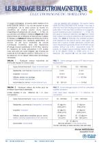
ELECTROMAGNETIC SHIELDING c) s’agit-il d’émissions, la source étant dedans et la limite prescrite dehors ? Ce cas est souvent le plus contraignant, car la paroi pourra se trouver en conditions de champ proche d’une source magnétique (impédances de circuits << 377Ω), ce qui donnera une réflexion médiocre (Figure 3) et des phénomènes de re-réflexions et résonances multiples à l’intérieur. Le tableau 2 indique les limites de champ rayonné imposées pour quelques applications. Là encore, on sait qu’un ensemble de circuits numériques modernes, avec des fréquences d’horloge toujours supérieures à 20-30...
Open the catalog to page 10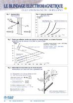
ELECTROMAGNETIC SHIELDING Fig. 1 Représentation Absorption loss Acier ordinaire ép. 1 mm Ordinary steel thickn. 1 mm Cuivre 0,8 mm ou Aluminium 1 mm Copper 0.8 mm or Aluminium 1 mm Condition champ lointain : d (m) > 48/F (MHz) (synonyme : onde plane) Fig. 3 Pertes par réflexion contre une source en champ lointain, ou champ H proche Reflection loss for source in far field, or near H-Field Ecran Cuivre / Copper screen Far field condition : d (m) > 48/F (MHz) (synonym : plane wave) Acier / Steel Champ H proche / Near H field m =1 r, d ppe Co re / 0 cm Cuiv =1 er, d p Cop m m re / 10 c =1 Cuiv d=...
Open the catalog to page 11All JACQUES DUBOIS catalogs and technical brochures
 RB METALLIC RIBBONS
2 Pages
 CONNECTOR GASKETS
2 Pages
 PROSIL
1 Page
 TISCAT
1 Page
 TRIMET
3 Pages
 CABSIL
1 Page
 TRIMAS
1 Page
 TRISIL
3 Pages
 TISMAT 3D
1 Page
 SOMIMAS
1 Page
 THERMOSILHEAT
1 Page
 ELASIL
4 Pages
 CEMABSORB
1 Page
 NEOSIL F
1 Page
 Metallic Ribbons
2 Pages
 VUSSIL
3 Pages
- Cable sleeve
- Protection sleeve
- Plastic seal
- Adhesive tape
- Polymer conduit
- Tubular sleeve
- Metal seal
- Flat gasket
- Gasket sheet
- Rubber seal
- Double-sided adhesive tape
- Elastomer seal
- Metal conduit
- Polyurethane seal
- VMQ seal
- Ventilation grill
- Stainless steel gasket
- Rectangular seal
- Metal ventilation grill
- Acrylic adhesive tape