11810 series
1 /4Pages

11810 series
1 /4Pages
Catalog excerpts

a xylem brandSELF-PRIMING PUMPS FEATURES Pump Body: Impeller: Shaft: Wearplate: Shaft Seal: Ports: Motor: Weight: Bronze Construction Jabsco Neoprene Compound Stainless Steel Shaft Protected by Stainless Steel Impeller Sleeve Replaceable Lip Type Both 3/4" Garden Hose External thread and 1/2" Internal Pipe thread 1/3 HP/1800 RPM, Continuous Duty 22 lbs (10 kg) Approx. Models 11810-0121, 11810-0241 VARIATIONS AVAILABLE model no. description Motor meets USCG Electrical Standards (Title 33, Chapter 1, Part 183; Subpart 1) for ignition protection on gasoline powered vessels. APPLICATIONS Ideal for Bilge Pumping, Bait Tank, Wash Downs, and General Marine Service. OPERATING INSTRUCTIONS 1. INSTALLATION - Pump may be mounted in any position without loss of efficiency; however, it is suggested that the pump head be down if vertical mounting is desired. The rotation of the motor shaft determines the location of the pump’s intake and discharge ports. Refer to the Dimensional Drawing. 2. DRIVE - Direct. 3. SELF-PRIMING - Pump will produce a suction lift approaching 10 feet when dry and a lift up to 22 feet when primed. BE SURE SUCTION LINES ARE AIR TIGHT or pump will not self-prime. 4. RUNNING DRY - Unit depends on liquid pumped for lubrication. DO NOT RUN DRY for more than 30 seconds. Lack of liquid will burn the impeller. 5. NOTICE - Do not pump solvents, thinners, highly concentrated or organic acids. Pump damage may result. If corrosive fluids must be handled, pump life will be prolonged if pump is flushed with water after each use or after each work day. 6. PRESSURES - For continuous operation, do not exceed 40 feet total developed head. 7. TEMPERATURE - Impeller supplied in pump is HEAD CAPACITY TABLE TOTAL HEAD1800 RPM kg per ft of Meters of psi sq cm Water Water_GPM LPM
Open the catalog to page 1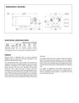
ELECTRICAL SPECIFICATIONS Total Wire Length1 - feet (meters) Pump AMP Fuse 0-10 11-20 21-35 Models Voltage Draw Size (0-3) (3-6) (6-11) WIRING Ensure wiring is adequate size to avoid a potential voltage drop by using the wire size specified in the Electrical Specifications Chart. It is recommended that a strain relief wire connector be installed in the rear end-bell protective cover to prevent electrical connections from being accidentally pulled loose. Remove the two cover retaining nuts and the protective cover. Select the type of strain relief wire connector to be used and remove...
Open the catalog to page 2
SERVICE INSTRUCTIONS DISASSEMBLY 1. Remove end cover screws, gasket and end cover. 2. Grasp impeller hub with water pump pliers and withdraw from body. 3. Loosen cam screw and remove cam. Clean off sealant. remove wearplate with screwdriver or hooked wire. 4. Loosen nut at body clamp. remove body from motor shaft. 5. Press out seal from motor mounting end of body towards impeller bore. 6. remove slinger from shaft. NoTE: Inspect all parts for wear or damage and replace if necessary. When returning to factory for repair, return the pump head only, unless motor replacement is required. ASSEMBLY...
Open the catalog to page 3
A. LIMITED WARRANTY: Jabsco warrants that at the time of shipment, the products manufactured by Jabsco and sold hereunder shall be in conformity with applicable written specifications and descriptions referred to or set forth herein, free from defects in material and, merchantable, and suitable for a particular purpose, provided such is implied by State law under the circumstances of this sale. 1. Jabsco agrees to repair or furnish a replacement for, but not to remove or install, any product or component thereof which, within one (1) year from date of purchase, shall upon test and examination by...
Open the catalog to page 4All Jabsco catalogs and technical brochures
 Automotive
12 Pages
 Flygt hydro turbines
8 Pages
 Heavy Duty Coils
4 Pages
 FanEx
FanEx4 Pages
 AirEx
AirEx2 Pages
 18940-0010
4 Pages
 59520 series
2 Pages
 Amazon Thrudeck
4 Pages
 18660-0121
4 Pages
 12210 Series
2 Pages
 36770 series
2 Pages
 35760 series
4 Pages
 35515-0010
2 Pages
 34739 Series
4 Pages
 Model 37202 Series
14 Pages
 Model 34600 Series
14 Pages
 Model 31705
4 Pages
 Hy~Line and Ultima Lobe Pumps
52 Pages
 GEAR PUPPY
2 Pages
 Model 18680-1000
4 Pages
 AMAZON MANUAL BILGE PUMPS
8 Pages
 Impeller Replacement
16 Pages
 Searchlights
12 Pages
 Ventilation Blowers
8 Pages
 Washdown Pumps
6 Pages
 Water Pressure Systems
16 Pages
 Toilet Systems
18 Pages
 Bilge Pumping Systems
38 Pages
 Flexible Impeller Pumps
40 Pages
 General Purpose Pumps
4 Pages
 Transfer Pumps
3 Pages
 Specialty Products
12 Pages
 Flexible Impeller Pumps part B
26 Pages
 Flexible Impeller Pumps part A
15 Pages
 Diaphragm & Drum Pumps
29 Pages
 Centrifugal Pumps
37 Pages


Archived catalogs
 Sliding Vane Pumps
10 Pages
 Oscillating Pumps
2 Pages
