X-Class HiPerFETTM Power MOSFET
1 /7Pages

X-Class HiPerFETTM Power MOSFET
1 /7Pages
Catalog excerpts
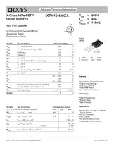
X-Class HiPerFET™ IXFH40N80XA Power MOSFET AEC Q101 Qualified N-Channel Enhancement Mode Avalanche Rated Fast Intrinsic Diode Advance Technical Information Test Conditions_Maximum Ratings TC= 25°C, Pulse Width Limited by TJM 80 A Maximum Lead Temperature for Soldering 300 °C Mounting Torque 1.13 / 10 Nm/lb.in Symbol Test Conditions Characteristic Values • International Standard Package • High Voltage Package Low RDS(ON) and Qg • Avalanche Rated • Low Package Inductance Advantages • High Power Density • Easy to Mount • Space Savings Applications • Switch-Mode and Resonant-Mode Power Supplies • DC-DC Converters • PFC Circuits • AC and DC Motor Drives • Robotics and Servo Controls © 2018 IXYS CORPORATION, All Rights Reserved
Open the catalog to page 1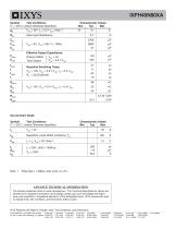
(TJ = 25°C, Unless Otherwise Specified) Min. Source-Drain Diode Symbol Test Conditions Characteristic Values (TJ = 25°C, Unless Otherwise Specified) Min. Note 1. Pulse test, t < 300ps, duty cycle, d < 2%. ADVANCE TECHNICAL INFORMATION The product presented herein is under development. The Technical Specifications offered are derived from a subjective evaluation of the design, based upon prior knowledge and experience, and constitute a "considered reflection" of the anticipated result. IXYS reserves the right to change limits, test conditions, and dimensions without notice. IXYS Reserves the Right...
Open the catalog to page 2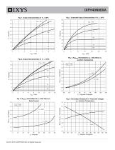
IXFH40N80XA Fig. 2. Extended Output Characteristics @ TJ = 25ºC Fig. 4. RDS(on) Normalized to ID = 20A Value vs. Junction Temperature Fig. 5. RDS(on) Normalized to ID = 20A Value vs. Drain Current Fig. 6. Normalized Breakdown & Threshold Voltages vs. Junction Temperature BVDSS / VGS(th) - Normalized RDS(on) - Normalized © 2018 IXYS CORPORATION, All Rights Reserved
Open the catalog to page 3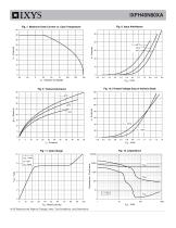
Fig. 7. Maximum Drain Current vs. Case Temperature 45 50 Fig. 10. Forward Voltage Drop of Intrinsic Diode Capacitance - PicoFarads IXYS Reserves the Right to Change Limits, Test Conditions, and Dimensions.
Open the catalog to page 4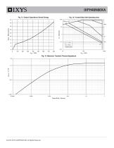
IXFH40N80XA Fig. 13. Output Capacitance Stored Energy Fig. 14. Forward-Bias Safe Operating Area 100 TC = 25 C Fig. 15. Maximum Transient Thermal Impedance Single Pulse Fig. 15. Maximum Transient Thermal Impedance aaaaa Pulse Width - Second © 2018 IXYS CORPORATION, All Rights Reserved
Open the catalog to page 5
IXYS Reserves the Right to Change Limits, Test Conditions, and Dimensions.
Open the catalog to page 6
Disclaimer Notice - Information furnished is believed to be accurate and reliable. However, users should independently evaluate the suitability of and test each product selected for their own applications. Littelfuse products are not designed for, and may not be used in, all applications. Read complete Disclaimer Notice at www.littelfuse.com/disclaimer-electronics.
Open the catalog to page 7All IXYS catalogs and technical brochures
 Polar3TM Power MOSFETs
2 Pages
 600V XPT IGBTs
2 Pages
 1200V XPT? IGBTs
2 Pages
 650V XPT? Trench IGBTs
2 Pages
 4500V POWER MOSFETs
2 Pages
 IXYS 2013
232 Pages
 BODO'S POWER SYSTEMS®
4 Pages
 IXYS News
6 Pages


Archived catalogs
 MICROCONTROLLERS Z8F0223QB005EG
245 Pages
 Selector guide
220 Pages
 IXYS RF Switch Mode MOSFET
2 Pages
 Breakover Diodes
8 Pages
 HiPerFETTM Power MOSFET
4 Pages
 NPT3 IGBT
4 Pages


- Technology switch
- Generator
- Multipole switch
- Transistor module
- Touch switch
- MOSFET transistor
- Bipolar transistor
- Microcontroller
- Digital generator
- IGBT transistor
- Analog microcontroller
- General purpose microcontroller
- Sensitive switch
- Programmable microcontroller
- Radio-frequency switch
- Substrate
- ADC microcontroller
- Semiconductor switch
- Photovoltaic solar cell
- Delay generator