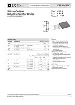
Silicon Carbide Schottky Rectifier Bridge

Silicon Carbide Schottky Rectifier Bridge
- Utilizes Silicon Carbide Schottky Diodes, which offer no reverse recovery at turn-off, soft turn-off waveform, and no forward recovery at turn-on.
- Switching behavior is independent of temperature, with low leakage current.
- The ISOPLUS i4-PAC™ package includes an isolated back surface, low coupling capacity between pins and heatsink, enlarged creepage towards heatsink, and application-friendly pinout, ensuring high reliability and industry-standard outline.
- Primarily used as output rectifiers in high-end switch mode power supplies.
- Suitable for other high-frequency rectifier applications.
- Maximum Ratings:
- Reverse Voltage (VRRM): 600 V
- Average Forward Current (IFAV): 3 A per diode
- Maximum Forward Surge Current (IFSM): 122 A at 25°C
- Total Power Dissipation (Ptot): 9 W per diode at 25°C
- Characteristic Values:
- Forward Voltage (VF): 0.7 V to 2.0 V depending on junction temperature
- Reverse Current (IR): 0.04 mA to 0.2 mA depending on junction temperature
- Junction Capacitance (CJ): 9 pF at 400 V
- Thermal Resistance (RthJC, RthJS): 8.5 K/W per diode
- Operating Temperature Range (TVJ): -40°C to +175°C
- Storage Temperature Range (Tstg): -40°C to +125°C
- Isolation Voltage (VISOL): 2500 V~
- Mounting Force with Clip: 20 - 120 N
- Coupling Capacity (Cp): 40 pF between shorted pins and mounting tab
- Dimensions: Pin-to-pin distance is 0.7 mm, pin-to-backside metal is 5.5 mm
- Weight: 9 g
Catalog excerpts
© 2008 IXYS All rights reserved - 2 20080602a FBS 10-06SC IXYS reserves the right to change limits, test conditions and dimensions. Advanced Technical Information Silicon Carbide Schottky Rectifier Bridge in ISOPLUS i4-PAC™ Features • Silicon Carbide Schottky Diodes - no reverse recovery at turn off - only charge of junction capacity - soft turn off waveform - no forward recovery at turn on - switching behaviour independent of temperature - low leakage current • ISOPLUS i4-PAC™ package - isolated back surface - low coupling capacity between pins and heatsink - enlarged creepage towards heatsink - application friendly pinout - high reliability - industry standard outline Applications • output rectifiers of high end switch mode power supplies • other high frequency rectifiers Rectifier Bridge Symbol Conditions Maximum Ratings VRRM 600 V IFAV ID(AV)M IFSM TC = 90°C; sine 180° (per diode) TC = 90°C TC = 25°C; t = 10 ms; sine 50 Hz 3 6.6 12 A A A Ptot TC = 25°C (per diode) 19 W Symbol Conditions Characteristic Values (TVJ = 25°C, unless otherwise specified) min. typ. max. VF IF = 4 A TVJ = 25°C TVJ = 125°C 1.7 1.9 2.0 V V IR VR = VRRM TVJ = 25°C TVJ = 125°C 0.04 0.2 mA mA CJ VR = 400 V TVJ = 125°C 9 pF RthJC RthJS (per diode) 11.5 8 K/W K/W VRRM = 600 V IdAVM = 6.6 A Cjunction = 9 pF 1 45 2 1 5
Open the catalog to page 1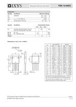
© 2008 IXYS All rights reserved - 2 20080602a FBS 10-06SC IXYS reserves the right to change limits, test conditions and dimensions. Advanced Technical Information Dimensions in mm (1 mm = 0.0394“) Die konvexe Form des Substrates ist typ. < 0,05 mm über der Kunststoffoberfläche der Bauteilunterseite The convex bow of substrate is typ. < 0.05 mm over plastic surface level of device bottom side Component Symbol Conditions Maximum Ratings TVJ Tstg operating -40...+175 -40...+125 °C °C VISOL IISOL < 1 mA; 50/60 Hz 2500 V~ FC mounting force with clip 20 - 120 N Symbol Conditions Characteristic Values...
Open the catalog to page 2All IXYS catalogs and technical brochures
 Polar3TM Power MOSFETs
2 Pages
 600V XPT IGBTs
2 Pages
 1200V XPT? IGBTs
2 Pages
 650V XPT? Trench IGBTs
2 Pages
 4500V POWER MOSFETs
2 Pages
 IXYS 2013
232 Pages
 BODO'S POWER SYSTEMS®
4 Pages
 IXYS News
6 Pages


Archived catalogs
 MICROCONTROLLERS Z8F0223QB005EG
245 Pages
 Selector guide
220 Pages
 IXYS RF Switch Mode MOSFET
2 Pages
 Breakover Diodes
8 Pages
 HiPerFETTM Power MOSFET
4 Pages
 NPT3 IGBT
4 Pages


- Technology switch
- Generator
- Multipole switch
- Transistor module
- Touch switch
- MOSFET transistor
- Bipolar transistor
- Microcontroller
- Digital generator
- IGBT transistor
- Analog microcontroller
- General purpose microcontroller
- Sensitive switch
- Programmable microcontroller
- Radio-frequency switch
- ADC microcontroller
- Semiconductor switch
- Photovoltaic solar cell
- Delay generator