NPT3 IGBT

NPT3 IGBT
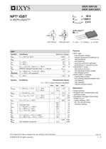
- NPT3 IGBT: Offers low saturation voltage, positive temperature coefficient for easy paralleling, fast switching, and short tail current for optimized performance in resonant circuits.
- HiPerFRED™ Diode: Features fast reverse recovery, low operating forward voltage, and low leakage current.
- ISOPLUS247™ Package: Provides an isolated back surface, low coupling capacity between pins and heatsink, high reliability, and conforms to industry standard outlines.
- Electrical Ratings: VCES = 1200 V, IC25 = 36 A, VCE(sat)typ = 2.4 V.
- Thermal Ratings: Maximum junction temperature (TVJ) and storage temperature (Tstg) range from -55°C to +150°C.
- Diode Characteristics: Maximum forward current IF25 = 25 A at 25°C, with a typical forward voltage VF of 2.6 V at 25°C.
- Switching Times: Includes turn-on and turn-off times with specific conditions provided for inductive loads.
- Thermal Impedance: Detailed thermal analysis model provided with transient thermal impedance characteristics.
Catalog excerpts
© 2008 IXYS All rights reserved - 4 20080118a IXER 20N120 IXER 20N120D1 IXYS reserves the right to change limits, test conditions and dimensions. NPT3 IGBT in ISOPLUS247™ Features • NPT3 IGBT - low saturation voltage - positive temperature coefficient for easy paralleling - fast switching - short tail current for optimized performance in resonant circuits • HiPerFRED™ diode - fast reverse recovery - low operating forward voltage - low leakage current • ISOPLUS247™ package - isolated back surface - low coupling capacity between pins and heatsink - high reliability - industry standard outline Applications • single switches • choppers with complementary free wheeling diodes • phaselegs, H bridges, three phase bridges e.g. for - power supplies, UPS - AC, DC and SR drives - induction heating IC25 = 36 A VCES = 1200 V VCE(sat)typ = 2.4 V ISOPLUS247™ Isolated Backside E C G C G E C G E IXER 20N120 IXER 20N120D1 IGBT Symbol Conditions Maximum Ratings VCES TVJ = 25°C to 150°C 1200 V VGES ± 20 V IC25 IC90 TC = 25°C TC = 90°C 29 19 A A ICM VCEK VGE = ±15 V; RG = 68 W; TVJ = 125°C RBSOA Clamped inductive load; L = 100 ìH 40 VCES A tSC (SCSOA) VCE = 900 V; VGE = ±15 V; RG = 68 W TVJ = 125°C; non-repetitive 10 ìs Ptot TC = 25°C 130 W Symbol Conditions Characteristic Values (TVJ = 25°C, unless otherwise specified) min. typ. max. VCE(sat) IC = 20 A; VGE = 15 V; TVJ = 25°C TVJ = 125°C 2.4 2.8 2.8 V V VGE(th) IC = 0.6 mA; VGE = VCE 4.5 6.5 V ICES VCE = VCES; VGE = 0 V; TVJ = 25°C TVJ = 125°C 0.2 0.2 mA mA IGES VCE = 0 V; VGE = ± 20 V 200 nA td(on) tr td(off) tfE on Eoff Inductive load L = 100 ìH; TVJ = 125°C VCE = 600 V; IC = 25 A VGE = ±15 V; RG = 68 . 205 105 320 175 4.1 1.5 ns ns ns ns mJ mJ Cies QGon VCE = 25 V; VGE = 0 V; f = 1 MHz VCE = 600 V; VGE = 15 V; IC = 20 A 1.2 100 nF nC RthJC RthCH with heatsink compound 0.5 0.96 K/W K/W G = Gate C = Collector E = Emitter
Open the catalog to page 1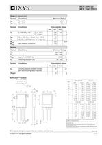
© 2008 IXYS All rights reserved - 4 20080118a IXER 20N120 IXER 20N120D1 IXYS reserves the right to change limits, test conditions and dimensions. Diode [D1 version only] Symbol Conditions Maximum Ratings IF25 IF90 TC = 25°C TC = 90°C 25 15 A A Symbol Conditions Characteristic Values min. typ. max. VF IF = 20 A; VGE = 0 V; TVJ = 25°C TVJ = 125°C 2.6 2.0 3.0 V V IRM trr VR = 600 V; L = 100 ìH; TVJ = 125°C diF /dt = -400A/ìs; IF = 15 A; VGE = 0 V 16 130 A ns RthJC RthCH with heatsink compound 2.3 1.3 K/W Symbol Conditions Characteristic Values min. typ. max. CP coupling capacity between shorted...
Open the catalog to page 2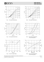
© 2008 IXYS All rights reserved - 4 20080118a IXER 20N120 IXER 20N120D1 IXYS reserves the right to change limits, test conditions and dimensions. 0 200 400 600 800 1000 0 10 20 30 40 0 50 100 150 200 0 1 2 3 4 5 6 0 20 40 60 80 0 20 40 60 80 100 0 3 6 9 12 15 0 1 2 3 4 5 6 0 10 20 30 40 50 60 VCE [V] IC [A] -di/dt [A/ìs] IRM [A] trr [ns] FII30-12E IRM trr 9 V 11 V 11 V 0 5 10 15 20 0 20 40 60 80 0 1 2 3 4 0 10 20 30 40 50 IF [A] 9 V 13 V 13 V 15 V TVJ = 25°C TVJ = 125°C VCE = 20 V TVJ = 125°C TVJ = 25°C TVJ = 125°C VR = 600 V IF = 15 A TVJ = 25°C VGE = 17 V VGE = 17 V TVJ = 125°C VCE = 600 V...
Open the catalog to page 3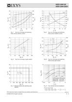
© 2008 IXYS All rights reserved - 4 20080118a IXER 20N120 IXER 20N120D1 IXYS reserves the right to change limits, test conditions and dimensions. 0 10 20 30 40 0 4 8 12 16 20 0 50 100 150 200 250 0 10 20 30 40 0.0 0.5 1.0 1.5 2.0 2.5 3.0 3.5 4.0 0 50 100 150 200 250 300 350 400 0.001 0.01 0.1 1 10 0.1 1 10 0 50 100 150 200 250 0.0 0.5 1.0 1.5 2.0 2.5 0 250 500 750 1000 1250 0 50 100 150 200 250 0 2 4 6 8 10 0 200 400 600 800 1000 1200 1400 0 10 20 30 40 50 Eoff td(off) tf Eon tr Eoff td(off) tf IC [A] A Eoff [mJ] Eon [mJ] t [ns] RG [..] VCE [V] t [ms] ICM [A] ZthJH [K/W] td(on) VCE = 600 V VGE...
Open the catalog to page 4All IXYS catalogs and technical brochures
 Polar3TM Power MOSFETs
2 Pages
 600V XPT IGBTs
2 Pages
 1200V XPT? IGBTs
2 Pages
 650V XPT? Trench IGBTs
2 Pages
 4500V POWER MOSFETs
2 Pages
 IXYS 2013
232 Pages
 BODO'S POWER SYSTEMS®
4 Pages
 IXYS News
6 Pages


Archived catalogs
 MICROCONTROLLERS Z8F0223QB005EG
245 Pages
 Selector guide
220 Pages
 IXYS RF Switch Mode MOSFET
2 Pages
 Breakover Diodes
8 Pages
 HiPerFETTM Power MOSFET
4 Pages


- Technology switch
- Generator
- Multipole switch
- Transistor module
- Touch switch
- MOSFET transistor
- Bipolar transistor
- Microcontroller
- Digital generator
- IGBT transistor
- Analog microcontroller
- General purpose microcontroller
- Sensitive switch
- Programmable microcontroller
- Radio-frequency switch
- Substrate
- ADC microcontroller
- Semiconductor switch
- Photovoltaic solar cell
- Delay generator