HiPerFETTM Power MOSFET

HiPerFETTM Power MOSFET
- Maximum Ratings: VDSS = 100 V, ID25 = 75 A, RDSon = 25 mΩ, trr < 200 ns.
- Temperature Ratings: Operating junction temperature (TVJ) from -40°C to +150°C, storage temperature (Tstg) from -40°C to +125°C.
- Isolation Voltage: VISOL = 3600 V~.
- Mounting Torque: 1.5 - 2.0 Nm.
- Threshold Voltage (VGS(th)): 2.0 to 4 V.
- Gate-Source Leakage Current (IGSS): ±100 nA.
- Drain-Source Leakage Current (IDSS): 250 µA at 25°C, 1 mA at 125°C.
- Input Capacitance (Ciss): 4500 pF.
- Switching Times: td(on) = 20-30 ns, tr = 60-110 ns, td(off) = 80-110 ns, tf = 60-90 ns.
- Low RDSon and gate charge for high-frequency operation.
- Unclamped inductive switching capability and dv/dt ruggedness.
- Fast intrinsic reverse diode.
- Isolated back surface and application-friendly pinout in ECO-PAC 2 package.
- Output Characteristics: Shows the relationship between VDS and ID.
- Input Admittance: Illustrates the input capacitance behavior.
- RDS(on) vs. Drain Current: Displays how RDS(on) changes with varying drain current.
- Temperature Dependence: Graphs show how RDS(on) and breakdown voltage vary with temperature.
- Gate Charge and Capacitance Curves: Provide insights into the gate charge characteristics and capacitance variations.
Catalog excerpts

© 2005 IXYS All rights reserved 1 - 4 VKM 60-01P1 515 ID25 = 75 A VDSS = 100 V RDSon = 25 mÙ trr < 200 ns HiPerFETTM Power MOSFET H-Bridge Topology in ECO-PAC 2 N-Channel Enhancement Mode High dv/dt, Low trr, HDMOSTM Family MOSFETs Symbol Conditions Maximum Ratings VDSS TJ = 25°C to 150°C 100 V VDGR TJ = 25°C to 150°C; RGS = 1 MÙ 100 V VGS Continuous ±20 V VGSM Transient ±30 V ID25 TC = 25°C 75 A IDM TC = 25°C, pulse width limited by TJM 300 A IAR TC = 25°C 75 A EAR TC = 25°C 30 mJ dv/dt IS IDM, di/dt 100 A/ìs, VDD VDSS, 5 V/ns TJ 150°C, RG = 2 Ù PD TC = 25°C 300 W Symbol Conditions Characteristic Values (TJ = 25°C, unless otherwise specified) min. typ. max. VDSS VGS = 0 V, ID = 250 ìA 100 V VGS(th) VDS = VGS, ID = 4 mA 2.0 4 V IGSS VGS = ±20 VDC, VDS = 0 ±100 nA IDSS VDS = 0.8 • VDSS; TJ = 25°C 250 ìA VGS = 0 V; TJ = 125°C 1 mA RDS(on) VGS = 10 V, ID = 0.5 ID25 25 mÙ Pulse test, t < 300 ìs, duty cycle d < 2% gfs VDS = 10 V; ID = ID25, pulse test 25 30 S Ciss 4500 pF Coss VGS = 0 V, VDS = 25 V, f = 1 MHz 1600 pF Crss 800 pF td(on) 20 30 ns tr VGS = 10 V, VDS = 0.5 • VDSS, ID = 0.5 ID25 60 110 ns td(off) RG = 2 Ù, (External) 80 110 ns tf 60 90 ns Qg(on) 180 260 nC Qgs VGS = 10 V, VDS = 0.5 • VDSS, ID = 0.5 ID25 36 70 nC Qgd 85 160 nC RthJC 0.5 K/W RthCK with heatsink compound (0.42 K/m.K; 50 ìm) 0.25 K/W Features • HiPerFETTM technology - low RDSon - low gate charge for high frequency operation - unclamped inductive switching (UIS) capability - dv/dt ruggedness - fast intrinsic reverse diode • ECO-PAC 2 package - isolated back surface - enlarged creepage towards heatsink - application friendly pinout - low inductive current path - high reliability - solderable pins for PCB mounting Applications • drives and power supplies • battery or fuel cell powered • automotive, industrial vehicle etc. • secondary side of mains power supplies IXYS reserves the right to change limits, test conditions and dimensions. Pin arangement see outlines L 4 L 9 P 18 R 18 X 15 T 18 V 18 A1 E10 F10 K10 K 12 K 13 NTC L 6 X 18
Open the catalog to page 1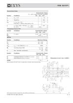
© 2005 IXYS All rights reserved 2 - 4 VKM 60-01P1 515 Module Symbol Conditions Maximum Ratings TVJ -40...+150 °C Tstg -40...+125 °C VISOL IISOL 1 mA; 50/60 Hz; t = 1 s 3600 V~ Md mounting torque (M4) 1.5 - 2.0 Nm 14 - 18 lb.in. a Max. allowable acceleration 50 m/s2 Symbol Conditions Characteristic Values min. typ. max. dS Creepage distance on surface (Pin to heatsink) 11.2 mm dA Strike distance in air (Pin to heatsink) 11.2 mm Weight 24 g Source-Drain Diode Characteristic Values (TJ = 25°C, unless otherwise specified) Symbol Conditions min. typ. max. IS VGS = 0 V 75 A ISM Repetitive; 300 A VSD...
Open the catalog to page 2All IXYS catalogs and technical brochures
 Polar3TM Power MOSFETs
2 Pages
 600V XPT IGBTs
2 Pages
 1200V XPT? IGBTs
2 Pages
 650V XPT? Trench IGBTs
2 Pages
 4500V POWER MOSFETs
2 Pages
 IXYS 2013
232 Pages
 BODO'S POWER SYSTEMS®
4 Pages
 IXYS News
6 Pages


Archived catalogs
 MICROCONTROLLERS Z8F0223QB005EG
245 Pages
 Selector guide
220 Pages
 IXYS RF Switch Mode MOSFET
2 Pages
 Breakover Diodes
8 Pages
 NPT3 IGBT
4 Pages


- Technology switch
- Generator
- Multipole switch
- Transistor module
- Touch switch
- MOSFET transistor
- Bipolar transistor
- Microcontroller
- Digital generator
- IGBT transistor
- Analog microcontroller
- General purpose microcontroller
- Sensitive switch
- Programmable microcontroller
- Radio-frequency switch
- Substrate
- ADC microcontroller
- Semiconductor switch
- Photovoltaic solar cell
- Delay generator