Catalog excerpts

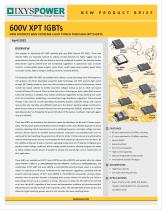
Efciency Through Technology NEW DISCRETE 600V EXTREME LIGHT PUNCH THROUGH XP IXYS expands its benchmark XPT IGBT portfolio with new 600V discrete XPT IGBTs. These new discrete IGBTs are especially tailored to address market demands for highly rugged, low loss semiconductor devices that oer the ability to be easily congured in parallel. The featured devices demonstrate superior performance and exceptional ruggedness in applications such as power inverters, uninterruptible power supplies, motor drives, switch mode power supplies, power factor Type MMIX SMPD correction circuits, battery chargers, welding machines, and lamp ballasts. The introduced 600V XPT IGBTs are available with collector current (Ic) ratings from 100 Amperes to 210 Amperes (Tc=25oC). Developed using thin wafer technology and IXYS’ extreme light punch through (XPT) design platform, these new devices feature excellent electrical characteristics which include low typical collector to emitter saturation voltages (Vcesat as low as 1.8V), low typical current fall times (tfi as low as 42ns), and low typical turn-o energy per pulse values (Eo as low as 0.33mJ @ Tj=25oC). In addition, they exhibit exceptional ruggedness during switching and under short circuit conditions, establishing a new benchmark regarding device ruggedness. This is achieved through a 10us short circuit safe operating area (SCSOA), dynamic avalanche ratings, and a square reverse bias safe operating area (RBSOA) rated up to the device’s blocking voltage. Furthermore, these devices feature an extended forward bias safe operating area (FBSOA), allowing for a “wider operating window” as dictated by the power limitations of the device, resulting in improved ruggedness and reliability. These new IGBTs are available in two distinctive speed classications; the B3 and C3 Classes respectively. The B3 and C3 speed classications present designers with a more exible approach to device selection regarding critical requirements such as switching frequency, saturation voltage, and cost. B3-Class devices feature an excellent balance between conduction and switching losses and are B3 class op mized for 10-30khz switching optimized for hard switching frequencies from 10 kHz to 30 kHz. C3-Class devices are optimized for C3 class op mized for 20-60khz switching minimal switching losses and are recommended for hard switching frequencies from 20 kHz to 60 Square RBSOA kHz. Additional features include a maximum operating temperature of 175 degree Centigrade and a positive forward voltage coecient, which enables parallel operation, allowing designers the ability to utilize multiple discrete devices in parallel to achieve the desired high current requirements of their application. These IGBTs are available with IXYS’ Sonic-FRDTM and HiPerFREDTM anti-parallel ultra-fast diodes (Sonic-FRDTM – Sux H1, ie. IXXK100N60C3H1) (HiPerFREDTM – Sux D1, ie. IXXH50N60C3D1). The combination of XPT IGBT and Sonic-FRDTM or HiPerFREDTM ultra-fast diodes result in an optimal match for reduced turn-o losses. Furthermore the high dynamic ruggedness, combined with the smooth switching behavior of IXYS’ Sonic-FRDTM or HiPerFREDTM anti-parallel ultra-fast diodes provides users the greatest freedom in designing their systems without the need for any dV/dt or peak-voltage limiters such as snubbers or clamps. Moreover, it allows the XPT IGBT to be switched on at very high di/dt’s regardless of low current and temperature condition and provides excellent EMI performance despite the level of the switched current. The extended SOA of these devices also allows for higher switching speeds, which in turn translate into lower switching losses. Avalanche Rated Short Circuit Capability High Current Capability Op onal An parallel Ultrafast Diode Int onal Standard Packages ADVANTAGES High Power density Low Gate Drive Requirement APPLICATIONS Power Inverter chargers, Welding Machines, Lamp ballasts and Motor Drives
Open the catalog to page 1
600V XPT IGBT Summary Table Part Number Package Style on Circuits Application Circuits Legend Power Supply Input Mains 90VAC – 265VAC Power Factor Power Factor Figure 2: TIG Welding Inverter Figure 1: Electronic Lamp Ballast Figure 1 illustrates a simplied (medium-power) electronic lamp ballast circuit. This electronic lamp ballast circuit topology consists of a primary rectier, power factor correction circuit, control unit (Power supply, MCU, and Gate Drivers), half-bridge inverter and a resonant output stage. Two IXXH50N60C3D1 XPT IGBTs (Q1 & Q2) are paired to form the half-bridge power...
Open the catalog to page 2All IXYS catalogs and technical brochures
-
Polar3TM Power MOSFETs
2 Pages
-
1200V XPT? IGBTs
2 Pages
-
650V XPT? Trench IGBTs
2 Pages
-
4500V POWER MOSFETs
2 Pages
-
IXYS 2013
232 Pages
-
BODO'S POWER SYSTEMS®
4 Pages
-
IXYS News
6 Pages
Archived catalogs
-
MICROCONTROLLERS Z8F0223QB005EG
245 Pages
-
Selector guide
220 Pages
-
Breakover Diodes
8 Pages
-
NPT3 IGBT
4 Pages
-
IXYS RF Switch Mode MOSFET
2 Pages
-
HiPerFETTM Power MOSFET
4 Pages


