Dynamelt M35

Dynamelt M35
1 / 219 PagesView full catalog

Dynamelt M35

Product catalog summary
Overview: The document is an operations and service manual for the DYNAMELT M35 DCL Adhesive Supply Unit (ASU) by ITW Dynatec, designed for operators and service personnel to ensure safe and efficient use of the equipment.
1. Safety Precautions: Emphasizes safety in operating the ASU, covering electrical safety, handling high temperatures and pressures, using protective covers, and wearing protective gear. It includes installation and operation safety, burn treatment, and lockout/tagout procedures.
2. Description & Specifications: Details the ASU's specifications, installation dimensions, wattage capacity, and circuit breaker identification. It defines the ASU code for ordering parts.
3. Installation & Start-Up: Guides users through installation and start-up, including unit placement, panel box door operation, user connections, adhesive formula changes, and controller calibration.
4. DynaControl Controller Set-Up: Explains temperature control functions, error indications, alarms, and system status lights, with settings for typical operations and programmable values.
5. Programming of DynaControl Controller: Covers programming and monitoring of the controller, including basic programming sequences, setup instructions, and service functions.
Conclusion: The manual is a comprehensive guide for the safe and efficient operation of the DYNAMELT M35 DCL ASU, providing detailed instructions on installation, operation, and maintenance.
Safety Precautions: Operators must read the manual before use. Maintenance should be by trained technicians. Electrical safety involves disconnecting power before servicing. High temperatures require protective gear. High pressure necessitates proper installation of covers and guards.
Installation and Operation Guidelines: Avoid hose kinking and heat contact. Ensure correct electrical connections and clean adhesive to prevent clogging. Hand-held applicators should not be pointed at people.
Burn Treatment: Burns from adhesives require treatment at a burn center. Safety gear is mandatory.
Service and Maintenance: Only qualified personnel should service the unit. Avoid explosive environments and use recommended cleaning compounds.
Lockout/Tagout Procedures: Follow OSHA guidelines for lockout procedures, being aware of stored energy.
Use of PUR Adhesives: Requires proper ventilation due to dangerous fumes.
Product Description and Specifications: The ASU is a computer-controlled hot-melt supply unit with flexible temperature programming, accurate control, and energy efficiency.
Technical Specifications: Includes environmental conditions, system support for hoses and heads, hopper capacity, and electrical specifications.
Performance and Control: Features temperature control range, scheduler, password protection, and communication capabilities.
Dimensions and Power: Provides installation dimensions and wattage capacity, with circuit breaker determination based on configuration.
Main Circuit Breaker Identification: Instructions for identifying the main circuit breaker in the ASU.
Specifications and Codes: Detailed specifications and codes for power configurations, drive setups, and component codes.
Installation Procedures: Steps for placing the ASU, ensuring power is off, and making connections.
Electrical and Adhesive Connections: Instructions for connecting hoses and electrical components.
Pressure Relief Valve Adjustment: Guide for adjusting the valve to protect the system from overload.
Adding and Changing Adhesive: Guidelines for maintaining adhesive levels and changing formulations.
Controller Options and Calibration: Procedures for installing and calibrating controller options.
Temperature Calibration and Adjustment: Procedure for recalibrating the pump enable thermostat.
Voltage Tachometer Calibration: Calibration of the tachometer for motor speed monitoring.
Tach Generator Installation and Calibration: Installation and calibration of the tach generator.
Level Control Adjustment: Adjustment of the level control device for adhesive levels.
Start-Up and Shut Down Procedures: Procedures for starting and shutting down the system.
Storage and Disposal: Instructions for temporary storage and disposal of the system.
Controller Setup and Temperature Control: Management of temperature settings and programming features.
Specifications: Communication support, character format, and DynaControl's role as a slave device.
Procedures: Setup of temperature zones and programming for system performance.
Error Indications & Alarms: Visual and audible alarms for errors, with troubleshooting steps.
System Status Lights: Tri-color stack light indicating system status.
Settings for Typical Operation: Recommended temperature settings for packaging operations.
Factory Programmed Values: Default and factory-programmed values for system parameters.
Communication Protocol: Instructions for using the serial protocol for system parameters.
EtherNet/IP Adapter Option: Optional adapter for remote monitoring and control.
Installation of EtherNet/IP-Adapter in ControlLogix5000 System: Steps for connecting and configuring the adapter.
Importing Controller Tags: Instructions for importing controller tag tables.
Communication Details: Details on controller tags and control settings.
IP-Address Configuration: Methods for changing the IP address.
Diagnostic LEDs: LED states indicating network and module status.
Configuration File: Editing the ethcfg.cfg file for network properties.
Word Address Functions: List of word addresses for setpoints and motor modes.
Overview: Detailed technical specifications and programming instructions for the DynaControl Controller.
Specifications: Temperature zones, pressure channels, and pump speed adjustments.
Data Tables: Detailed data tables for input and output areas.
Programming Instructions: Steps for setting up the controller and programming setpoints.
Controller Setup: Instructions for turning on the controller and setting temperature scales.
Monitoring and System Status: System status display and alarm indicators.
Temperature and Alarm Indicators: Indicators for temperature alarms and standby states.
Zone Status Display: Displays actual temperatures or status of zones.
7-Day Scheduler and Pump Information: Scheduler and pump mode settings.
Setpoints Programming: Programming of temperature zones and pump modes.
Pump Programming: Programming of pump modes and clutches.
Pressure Programming: Pressure screens and transducer calibration.
Service Functions: Programming of temperature deviation, standby temperature, and sleep mode.
Sequential Heating Programming: Programming options for sequential heating.
Temperature Scale and Security: Temperature scale settings and security features.
Service Functions: Programming for customer zone names and system logbook.
Main Scheduler Screen: Use of the main scheduler screen for automated control.
7-Day Scheduler: Programming of events for system alignment with production schedules.
PC Link and Data Transfer: Instructions for connecting to a remote PC for data transfer.
Overview: Instructions for operating, maintaining, and troubleshooting the DYNAMELT M ASU system.
Data Transfer Procedures: Steps for data transfer and file format details.
Preventive Maintenance: Regular cleaning and inspection tasks.
Troubleshooting: Self-diagnostics and error indication alarms.
Overview: Technical manual for troubleshooting and handling procedures for various components.
Key Sections: Temperature and communication errors, hopper and hose troubleshooting, motor speed control reset, safety precautions, handling PCBs, thermostat features, battery information, PCB layouts, motor control adjustments, and optional components.
Critical Information: Importance of safety and proper handling of components.
Overview: Technical manual for the DYNAMELT M ASU series, covering models DM35, DM70/140, and DM210.
Pressure PCB Specifications: Specifications for pressure PCBs and alarm outputs.
Heater and Sensor Resistance Values: Tables for resistance values of sensors and heaters.
Troubleshooting Procedures: Guide for diagnosing and resolving issues with sensors and heaters.
Key Tables and Data: Tables with resistance values for troubleshooting.
Safety Warnings: Warnings about high voltage and the need for qualified personnel.
Troubleshooting Procedures: Steps for verifying connections and inspecting components.
Adjustable Adhesive Pressure Relief Valve: Valve operation and adjustment for pressure relief.
Operation of the ASU’s Gear Pump: Manual and automatic operation of the gear pump.
Troubleshooting the ASU’s Gear Pump: Solutions for common pump problems.
Disassembly & Re-assembly Procedures: Instructions for accessing and replacing components.
Safety Precautions: Ensuring power is off before accessing components.
Assembly and Disassembly Procedures: Instructions for assembly and disassembly, including precautions.
Available Options and Accessories: List of options and accessories for system enhancement.
Pump Options and Accessories: Details on gear pumps and repair kits.
DynaControl Options: Enhancements for system monitoring and control.
Component Illustrations and Bills of Material: Exploded-view drawings and BOMs for maintenance and repair.
Key Recommendations: Recommendations for re-assembly and component inspection.
Component Illustrations & BOMs Overview: Detailed component illustrations and BOMs for assemblies.
1. Filter & Pressure Relief Assembly: Illustration and part numbers for the assembly.
2. Electrical Panel Box Assembly: BOM for electrical panel box components.
3. Cabinet Assembly: Details for cabinet assembly parts.
4. Drive Assemblies: Information on drive assemblies and components.
5. Pump Assemblies: Comprehensive BOMs for pump assemblies.
6. Assorted Pump Adapter Assemblies: Details on pump adapter assemblies.
Conclusion: Comprehensive guide for assembling and maintaining the DYNAMELT M ASU systems.
Introduction: Overview of Zenith Pumps' development of a rotary external gear pump.
Benefits: High accuracy, stable flows, and high temperature capability.
Specifications: Rotary external spur gear type with specific operating conditions.
Design: Simple design with precision construction.
Operation: Fluid transport and lubrication requirements.
Installation: Preparation and installation instructions.
Disassembly and Reassembly Procedures: Steps for disassembly and reassembly.
Troubleshooting Guide: Common issues and remedies.
Screw Torque Values: Torque values for screw sizes.
Preparation and Installation: Steps for preparing and installing the pump.
Cleaning and Maintenance: Maintenance requirements and cleaning methods.
Disassembly and Reassembly: Instructions for disassembly and reassembly.
Troubleshooting: Common issues and solutions.
Technical Specifications: Torque values and performance chart.
Description: Overview of ITW Dynatec’s metering gear pumps.
Health & Safety: Safety considerations for handling components.
Operation: Factors affecting pump operation.
Flushing: Flushing procedures to prevent contamination.
Filtration: Importance of filtration before the pump inlet.
Installation: Installation requirements and alignment.
Fixing and Lubrication: Securing and lubricating the pump.
Gland Leakage: Addressing gland leakage issues.
Problem-finding Chart: Common issues and remedies.
Cleaning: Cleaning procedures for components.
Maintenance: Maintenance guidelines and torque specifications.
Reconditioning: Returning the pump for overhauling.
Pump Shaft Seal Replacement: Procedure for replacing the pump shaft seal.
Rebuild Kit for 8.5cc TSHA Pump: Contents of the rebuild kit.
See more

Catalog excerpts

Dynamelt M35-46

Version: V5.00eDate: 09.27.01 OpcodeParameterSyntax*Return StringFunctionOption 0x41 / 'A'zz.n*ddddACK / NAKwrite temperature setpoints C (10 to 232) , will switch to Celsius 1 zone / multiple zones0x46 / 'F'zz.n*ddddACK / NAKwrite temperature setpoints аF (50 to 450), will switch to Fahrenheit1 zone / multiple zones0x61 / 'a'zzdddd (n*dddd)read temperature setpoints1 zone / all zones 0x64 / 'd'zzdddd (n*dddd)read actual temperature (1999 = open sensor, 0999 = shorted sensor)1 zone / all zones0x42 / 'B'zz.n*ddACK / NAKwrite temperature tolerance window (5 to 50 degree)1 zone / multiple zones0x62...

 Open the catalog to page 46
Dynamelt M35-47

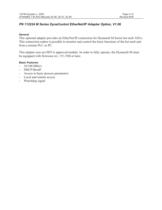
13ITW Dynatec c. 2005 Page 4-13 DYNAMELT M ASU Manuals 20-36, 20-37, 20-38 Revised 8/05 PN 112224 M Series DynaControl EtherNet/IP Adapter Option, V1.06 > General This optional adapter provides an EtherNet/IP connection for Dynamelt M Series hot melt ASUs. This connection makes it possible to monitor and control the basic functions of the hot melt unit from a remote PLC or PC.This adapter uses an ODVA approved module. In order to fully operate, the Dynamelt M must be equipped with firmware rev. V5.15M or later. > Basic Features: -10/100 Mbit/s -DHCP/BootP -Access to basic process parameters -Local...

 Open the catalog to page 47
Dynamelt M35-48

Page 4-14 ITW Dynatec c. 2005 Revised 8/05 DYNAMELT M ASU Manuals 20-36, 20-37, 20-38 Installing the EtherNet/IP-Adapter in a ControlLogix5000 System These installation steps assume that RSLogix5000 and ControlLogix5000 with an EtherNet/IP module/bridge (1756 ENBT or similar) are set up and working properly. 1.Connect the Dynatec Hot melt unit (ASU) to the Ethernet network using a standard RJ45-cable. 2. Start RsLogix5000 with a new or existing project. Set to OfflineӔ mode. 3. > Add the EtherNet/IP-Adapter to the PLC Configuration: OK 4. -Start by right clicking the EtherNet/IP module/bridge...

 Open the catalog to page 48
Dynamelt M35-49

15ITW Dynatec c. 2005 Page 4-15 DYNAMELT M ASU Manuals 20-36, 20-37, 20-38 Revised 8/05 6. Importing Controller Tags Details on the Communication The CD-ROM that is provided with the EtherNet/IP option contains a pre-defined controller tag table. In order to save time, this table may be imported. -In the RSLogix5000 go offline -Select Tools -> Import Tags -Select the Dynatec-Controller-Tags_DMM. CSVӔ from the CD-ROM -Click Import -If the import was successful, the Report Window in the lower part of the screen should indicate 242 imported tags. -Go online again -Go back to the controller tag screen...

 Open the catalog to page 49
Dynamelt M35-50

Page 4-16 ITW Dynatec c. 2005 Revised 8/05 DYNAMELT M ASU Manuals 20-36, 20-37, 20-38 (ASCII MӔ). Local Access PUMP (OUT-word 63) does not have to be set.2. Automatic Mode: the pump speed is controlled via a 0 to 10V signal, connected to the hot melt machine. In order to activate this mode, the OUT-word 50 (for pump 1) must be set to 65 (ASCII AӔ). The pump speed, which follows the line speed can be read in IN-word 134 (for pump 1). This value shows 0.1% resolution. 3. Stop Mode: The pump is stopped. 4. Bus Mode: the pump speed is controlled via OUT-word 56 (for pump 1). Out-word 50 (for pump...

 Open the catalog to page 50
Dynamelt M35-51

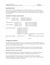
17ITW Dynatec c. 2005 Page 4-17 DYNAMELT M ASU Manuals 20-36, 20-37, 20-38 Revised 8/05 Identification Word OUT-word 79 is used as an identification word. This word must be set to a certain value to validate the communication. If this word is set differently, the hot melt unit will not accept the OUT area although the IN-area will show proper values. Dynamelt M hot melt units require ID- word set to 68. Examples for a typical communication Changing the IP-Address Initializing: Set OUT 76 to 1 : Switches the controller on Set OUT 79 to 68 : Identifies the communication Set OUT 77 to 0 : No standby,...

 Open the catalog to page 51
Dynamelt M35-52

Page 4-18 ITW Dynatec c. 2005 Revised 8/05 DYNAMELT M ASU Manuals 20-36, 20-37, 20-38 Using the Configuration File The file ethcfg.cfg can be used to change the IP-address. This method is possible only if the actual IP-address is known (e.g. the factory set 192.168.23.180), See also section Configuration FileӔ.-Open a FTP connection to the module (e.g. Windows Explorer FTP://192.168.23.180 )-Locate the ethcfg.cfg -Copy this file to a folder on your PC -Open the file with any text editor -Change the IP-address -Save the file using the same name -Copy the file back to the module -Re-cycle power...

 Open the catalog to page 52
Dynamelt M35-53

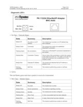
19ITW Dynatec c. 2005 Page 4-19 DYNAMELT M ASU Manuals 20-36, 20-37, 20-38 Revised 8/05 > Steady Off No power or no IP addressThe module has no power or no IP address has been assigned. Steady Green Connected The module has at least one established EtherNet/IP connection. Flashing Green No connections There are no EtherNet/IP connections established to the module. Flashing Red Connection Timeout One or more of the connections in which this module is the target has timed out. This state is only left if all timed out connections are re-established or if the module is reset. Steady Red Duplicate...

 Open the catalog to page 53
Dynamelt M35-54

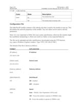
Page 4-20 ITW Dynatec c. 2005 Revised 8/05 DYNAMELT M ASU Manuals 20-36, 20-37, 20-38 GreenOff The module does not sense a link OnThe module has a link FORMAT EXPLANATION [IP address] > IP Address 192.168.23.180[Subnet mask] > Subnet mask 255.255.255.0 [Gateway address] > Gateway address 0.0.0. [DHCP/BOOTP] > DHCP/BootP ON > ON - Enabled > OFF Disabled [SPEED] > Speed Auto > Auto ֖ Default. Auto Negotiation will be used. > 100 Forces the module to operate at 100Mbit/s only > 10 ֖ Forces the module to operate at 10Mbit/s only >

 Open the catalog to page 54
Dynamelt M35-55

21ITW Dynatec c. 2005 Page 4-21 DYNAMELT M ASU Manuals 20-36, 20-37, 20-38 Revised 8/05 FORMAT EXPLANATION > SMTP server/ login settings > SMTP server/ login settings username > SMTP server/ login settings > Domain Name (Optional) > Host Name (Optional) >

 Open the catalog to page 55
Dynamelt M35-56

0Reserved1Reserved2Setpoint Premelt 13Setpoint Premelt 24Setpoint Premelt 35Setpoint Premelt 46Setpoint Premelt 57Setpoint Premelt 68Setpoint Progmelt 19Setpoint Progmelt 210Setpoint Progmelt 311Setpoint Filterblock 112Setpoint Filterblock 213Setpoint Filterblock 314Setpoint Hose 115Setpoint Hose 216Setpoint Hose 317Setpoint Hose 418Setpoint Hose 519Setpoint Hose 620Setpoint Hose 721Setpoint Hose 822Setpoint Hose 923Setpoint Hose 1024Setpoint Hose 1125Setpoint Hose 1226Setpoint Head 127Setpoint Head 228Setpoint Head 329Setpoint Head 430Setpoint Head 531Setpoint Head 632Setpoint Head 733Setpoint...

 Open the catalog to page 56

All ITW Dynatec catalogs and technical brochures

  1. APEX™

    2  Pages

  2. Dynamelt™ D

    2  Pages

  3. Dynamini™

    2  Pages

  4. Ultra™ SCS

    2  Pages

  5. Velocity™

    2  Pages

  6. TPC-2

    2  Pages

  7. TPC-9

    2  Pages

  8. DY2008

    2  Pages

  9. EVC-1

    2  Pages

  10. ADS1

    2  Pages

*Prices are pre-tax. They exclude delivery charges and customs duties and do not include additional charges for installation or activation options. Prices are indicative only and may vary by country, with changes to the cost of raw materials and exchange rates.