
- Catalogs
- ITT Cannon
- Rack & Panel Connectors Catalog

- Products
- Catalogs
- News & Trends
- Exhibitions
Rack & Panel Connectors Catalog

Rack & Panel Connectors Catalog
ITT Electronic Components, a division of ITT Corporation, offers a range of Cannon Rack and Panel connectors known for high reliability and quality, adhering to Six Sigma principles. These connectors are used in aerospace, defense electronics, and medical electronics markets.
ITT operates globally with facilities in the US, Europe, and Asia, using advanced technologies like robotic machining and automated testing to ensure quality and cost-effectiveness. The company emphasizes Six Sigma and Value Based Management in product development.
ITT provides custom interconnect solutions for harsh environments, working with customers to modify standard designs or create new solutions for reliability and cost-effectiveness.
ITT's connectors comply with the EU's RoHS directive, offering plating finishes like electroless nickel and gold plating to replace hazardous substances.
The document details connector series such as BKAD/E/F (ARINC 600) and DPXNE/NA (MIL-C-81659), including contact materials, shell materials, and military standards compliance. Connectors are available in various configurations for specific applications like space.
A guide is provided for ordering connectors, specifying series, shell size, contact type, and other modifiers, including polarizing positions and contact finishes.
- Low insertion force contacts
- Field replaceable inserts
- Compatibility with existing systems
- Various contact styles including crimp and solder-tail
ITT's Cannon Rack and Panel connectors are engineered for high performance and reliability, suitable for a wide range of applications, meeting industry standards and customer needs.
Instructions include using specific tools for crimping and extraction, with components shipped unassembled. Detailed assembly instructions are provided for coaxial cables and connectors.
Dimensions are provided in inches and millimeters, with cross-reference tables for military and Cannon part numbers.
The document provides part numbers for military and aerospace connectors, focusing on the DPX series, with cross-references, specifications, and dimensions.
Details on DPX series connectors, including materials, finishes, and compliance with military standards like MIL-C-81659 and ARINC 404.
Instructions for mounting and assembling connectors, including the use of specific tools and adherence to military specifications for reliability.
Suggestions for cable types and tools for optimal performance, emphasizing the importance of correct polarizing post positioning and adherence to dimensions and tolerances.
Details on junction shells, dust caps, and sealing plugs, with part numbers and dimensions for compatibility with DPX series connectors.
Tables include detailed measurements for connector components, with diagrams illustrating panel cutouts and connector assemblies.
Emphasis on correct polarizing post positioning, adherence to specified dimensions and tolerances, and the use of recommended tools for reliability and performance.
Safety precautions include avoiding use on the current supply side to prevent electric shock and warnings about toxic fumes during incineration of certain materials.
ITT provides a limited warranty, advising against deviations from specified operating conditions and recommending consultation of the latest data sheets for accurate information.
Contact information for ITT's customer support in Asia, Germany, Italy, the UK, and the USA is provided for global assistance and inquiries.
Catalog excerpts

Electronic Components Cannon Rack & Panel Connectors Customer Support Locations ASIA Tuopandun Industrial Area, Jinda Cheng, Xiner Village, Shajing Town, Baoan District, Shenzhen City, Guangdong, China 518125 Phone: 86.755.2726.7238 Fax: 86.755.2726.7515 GERMANY Cannonstrasse 1 Weinstadt, 71384 phone: 49.7151.699.0 fax: 49.7151.699.217 ITALY Corso Europa 41/43 Lainate (MI), Italy 20020 phone: 39.02938721 fax: 39.0293872300 UK Jays Close, Viables Estate Basingstoke, RG22 4BA phone: 44.1256.311200 fax: 44.1256.323356 USA 666 East Dyer Road Santa Ana, CA 92705 toll free: 1.800.854.3028 phone: 1.714.557.4700 fax: 1.714.628.2142 ©2007 ITT Corporation. “Engineered for life” and “Cannon” are registered trademarks of ITT Corporation. Specification and other data are based on information available at the time of printing, and are subject to change without notice. CRP-sept 07 Cannon Rack & Panel Connectors
Open the catalog to page 1
Cannon Rack and Panel ITT Electronic Components is a division of the multinational ITT Corporation a $7.5 billion dollar global enterprise. Our connector portfolio remains the most extensive in the industry offering the most reliable and cost effective range of interconnect solutions. These innovations have enabled ITT to provide products and technologies to such markets as: products at market driven prices. Our capabilities, especially in robotics, computerized precision tooling, Kaizen Project Management, Six Sigma tools, and test labs, gives ITT the most optimized global manufacturing footprint...
Open the catalog to page 2
Cannon Rack and Panel BKAD/E/F ARINC 600 Current Rating Contact Resistance Contact Material Shell Material Aluminum Alloy Aluminum Alloy Aluminum Alloy Aluminum Alloy Aluminum Alloy Aluminum Alloy Space Applications Page Number * RoHS compatible connectors are available upon request see “How to Order”guides for specific call outs for each product line. ** Note MIL-C-81659, MIL-C-83733 and MIL-C-39029, the US Government no longer maintains these documents, various standards agencies have assumed the role of maintaining these standards however, there can be differences in these “commercial” versions....
Open the catalog to page 3
Low insertion force contacts. Both environmental and non- environmental versions. Polarizing posts that are removable from the mating face. Field replaceable inserts for size 22 and power contacts. Up to 800 size 22 contacts in one connector. Crimp, coax, power, printed circuit and wire wrappable post style contacts. Uses standard DPX crimp, insertion/extraction tooling. Waveguide connections available. Rear Release/Rear Removable Size 12, 16, 20, 22 Crimp Contacts Front Release/Front Removable Size 22 Solder Tail and Wrap Post Contacts BKAD/E connectors represent the standard for new avionic...
Open the catalog to page 4
CONNECTOR SERIES RoHS CLASS SHELL SIZE CONNECTOR LAYOUT DESCRIPTION SIZE 1 COAX INSERT MODIFIER SHELL STYLE CONNECTOR MOUNTING MODIFIER POLARIZING POSITION MODIFIER (Contact, Finish, Material) * = For Polarizing Position greater then 99, add third digit. SHELL STYLE CONNECTOR SERIES 3 - Plug (rack side) 4 - Receptacle (box side) BKA (Per ARINC 600) RoHS version - RoHS compatible CONNECTOR MOUNTING MODIFIER - Non-environmental (rear release, crimp - Environmental (rear release, crimp contacts) - Non-environmental (front release, solder and wrap post #22 contact, rear release SHELL SIZE - Max....
Open the catalog to page 5
CONNECTOR LAYOUT DESCRIPTION Note: All layouts with "OPEN' insert cavity are not supplied with an insulator. If a Blank insert is required please consult factory. Three Digit Number Contained within the Shell Layout Indicates Total Number of Contacts Available (including Waveguide) NOTE. ANY OTHER COMBINATION OF INSERTS WITHIN A SPECIFIC SHELL IS AVAILABLE UPON REQUEST • • Layout included in the following ARINC configurations 707, 718 & 730. ■ • • Layout included in the following ARINC configurations 701, 702, 703, 704, 705, 706, 724, 725. • • • • Layout included in the following ARINC configurations...
Open the catalog to page 6
Shell Dimensions - Size 1 Plug BKAD SERIES 1.198 (30.43) MAX BKAE SERIES 1.550 (39.37) MAX Retainer Plate Panel Cutout * This dimension indicates distance from centerline of retaining screw to the centerline of first contact cavity. For further information, refer to ARINC 600 specification or consult factory. BKAE SERIES 1.531 (38.89) MAX BKAD/BKAF SERIES 1.221 (31.01) MAX Retainer Plate *This dimension indicates distance from centerline of retaining screw to the centerline of first contact cavity. For further information, refer to ARINC 600 specification or consult factory. Dimensions shown...
Open the catalog to page 7
Retainer Plate Panel Cutout * This dimension indicates distance from centerline of retaining screw to the centerline of first contact cavity. For further information, refer to ARINC 600 specification or consult factory. Retainer Plate Panel Cutout *This dimension indicates distance from centerline of retaining screw to the centerline of first contact cavity. For further information, refer to ARINC 600 specification or consult factory. Dimensions shown in inch (mm) Specifications and dimensions subject to change
Open the catalog to page 8
Retainer Plate Panel Cutout * This dimension indicates distance form centerline of retaining screw to the centerline of first contact cavity. For further information, refer to ARINC 600 specification or consult factory. BKAD/BKAF SERIES 1.317 (33.45)MAX BKAE SERIES 1.670 (42.42 )MAX Retainer Plate * This dimension indicates distance form centerline of retaining screw to the centerline of first contact cavity. For further information, refer to ARINC 600 specification or consult factory. Dimensions shown in inch (mm) Specifications and dimensions subject to change Panel Cutout
Open the catalog to page 9
Contact Arrangements - Shell Size 1 BKAD/BKAE (Plug Rear face shown) BKAF - Available Receptacle Shell Only (Front Release) Shell Cavity C ENGAGING END SURFACE WHITE ON RED TO INDICATE REAR SURFACE WHITE ON BLUE TO INDICATE REAR RELEASE REAR REMOVAL CONTACTS FRONT RELEASE FRONT REMOVAL CONTACTS (For Contact Cavity Location and Contact Cavity Identification refer to ARINC 600 or consult factory) Contact Arrangements - Shell Sizes 2 and 3 BKAD/BKAE (Plug Rear face shown) Shell Cavity C or F 1 6T6** 6 #8 TRIAX (Metallic Insert) **Pending ARINC release. NOTE: In layouts using #22 contacts mixed with...
Open the catalog to page 10All ITT Cannon catalogs and technical brochures
 Banding Adapters
2 Pages
 Tin Zinc J Plating
2 Pages
 MDSM Catalog
16 Pages
 Portfolio Catalog
63 Pages
 NEMESIS brochure
4 Pages
 CIR Series
218 Pages
 CGL Connectors
28 Pages
 CIR-M12 Databus Brochure
4 Pages
 CGE Catalog
8 Pages
 Chip-on-Flex Filter Catalog
6 Pages
 Trident Catalog
96 Pages
 Space Connectors Catalog
118 Pages
 DL Series ZIF Connectors Catalog
75 Pages
 PowerLock & SnapLock Catalog
39 Pages
 ComboD
103 Pages
 CMX FB
2 Pages
 CFast
CFast4 Pages
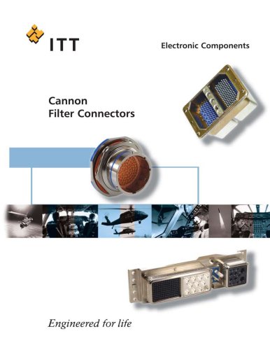 Filter full catalog
48 Pages
 D-Sub Full Line Catalog
302 Pages
 CACOM E
42 Pages
 CA Bayonet V2
68 Pages
 Audio XL
36 Pages
 APD
APD79 Pages


Archived catalogs
 Nemesis Full Line Catalog
44 Pages
- Data connector
- Electrical power supply connector
- Metal connector
- Circular connector
- Polymer connector
- Screw-in connector
- Socket electrical connector
- Industrial connector
- IP67 connector
- Rectangular connector
- Male connector
- RF connector
- Copper connector
- DIN connector
- Voltage connector
- Crimp connector
- Multipole connector
- Plug-in connector
- Coaxial connector