
- Catalogs
- ITT Cannon
- Fiber Optics Products and Design Guide Catalog

- Products
- Catalogs
- News & Trends
- Exhibitions
Fiber Optics Products and Design Guide Catalog

Fiber Optics Products and Design Guide Catalog
- Asia: Tuopandun Industrial Area, Shenzhen City, Guangdong, China. Tel: 86.755.2726.7238
- Germany: Cannonstrasse 1, Weinstadt. Tel: 49.7151.699.0
- Italy: Corso Europa 41/43, Lainate (MI). Tel: 39.02938721
- UK: Jays Close, Viables Estate, Basingstoke. Tel: 44.1256.311200
- USA (Cannon Products): 666 East Dyer Road, Santa Ana, CA. Toll-free: 1.800.854.3028
- USA (VEAM Products): 100 New Wood Road, Watertown, CT. Tel: 1.860.274.9681
ITT Electronic Components, a division of ITT Corporation, provides interconnect solutions for markets such as aerospace, defense electronics, and telecom systems, emphasizing high-quality standards through Six Sigma principles.
- Introduction to Fiber Optics: Covers the history and development of fiber optics, noting the breakthrough in glass purity by Corning scientists in 1970.
- How Optical Fiber Works: Explains total internal reflection and the structure of optical fibers, including core, cladding, and coating.
- Types of Fibers: Differentiates between singlemode and multimode fibers, their applications, and sizes.
- Cable Designs: Describes loose-tube and tight-buffered cable designs, their uses, and construction details.
- Connectors: Overview of product specifications and application guides.
- Cable/Harness Assemblies: Details on build-to-order options and typical configurations.
- Ground Tactical/Dock Side: Solutions for rugged environmental interconnects.
- Hybrid Connector Applications: Solutions for fiber channels in standard electrical connectors.
- Ground/Air Communication: High-density, small form factor optical contact systems.
- Shipboard/Dock Side: Standard naval and military/aerospace applications.
Fiber geometry, including cladding diameter, core/clad concentricity, and fiber curl, significantly impacts splicing and interconnect performance. Tightly controlled geometry tolerances improve coupling performance, reduce testing needs, and offer flexibility in equipment choice. Cladding diameter tolerance ensures consistent fiber size, reducing splice losses. Core/clad concentricity ensures the core is centered, minimizing splice loss. Fiber curl, caused by thermal stresses, must be controlled to prevent misalignment during splicing.
Key performance parameters for singlemode fibers include attenuation, dispersion, and mode-field diameter. Attenuation, measured in dB/km, is low in optical fibers, allowing long-distance signal transmission with fewer amplifiers. Dispersion, which affects data rate and distance, varies with wavelength. Chromatic dispersion includes material and waveguide dispersion, which can be balanced for optimal performance. Mode-field diameter affects bend-induced loss and splice loss, while cutoff wavelength determines singlemode operation.
Splicing and connectorizing are crucial for system performance and installation cost. Fusion splicing offers low-loss, nonreflective connections by fusing fiber ends. Mechanical splicing, used for emergency restoration, has improved performance but typically higher losses. Connectors provide remateable connections for system flexibility. Commercial connectors, like LC and MU, offer low insertion losses. Specialized connectors, based on Mil-T-29504, are used in severe environments.
ITT offers fiber optic interconnect solutions for various applications. The Cannon FOMC and ITAC connector systems are designed for field tactical use, adhering to MIL-PRF-83526 standards.
- Fiber Size and Ferrule I.D.: The document lists various fiber sizes and corresponding ferrule internal diameters for singlemode and multimode fibers, with specific dash numbers for identification.
- Terminus Size: Available in sizes 16 and 22, with modification codes available upon consultation with the factory.
- Material and Finish: Ferrules are made of zirconia ceramic, while terminus assemblies use brass alloy with gold plating. Other components use aluminum alloy with electroless nickel or cadmium plating.
- Insertion/Removal Tools: Specific tools are recommended for different terminus sizes, including metal and plastic options.
- Assembly and Termination: Consultation with the factory is advised for assembly and termination tools or factory-built cable assemblies.
- The PHD38999 series meets MIL-DTL-38999 envelope dimensions and includes features like EMI suppression, terminus stability, and removable alignment insert assemblies.
- It supports a variety of fiber buffering and jackets, with standard 38999 keys and metallic backshells with sealing grommets.
- Details on connector assembly for size #22 and #16 contact matrices are provided, including sample part numbers, cavity layouts, and thread specifications.
- Optional insert assemblies can be added to either the plug or receptacle assembly but not both.
- Materials and Finishes: Components are made from aluminum alloy with electroless nickel plating, stainless steel, and ceramic for internal sleeves. Hardware is passivated stainless steel.
- Connector Types: Includes circular and rectangular connectors, panel mount series, and backplane connectors.
- Contact Matrices: Available in sizes #22 and #16, with varying cavity layouts and shell sizes.
- Tooling: Specific insertion and removal tools are required for assembly and maintenance, with part numbers provided for each tool.
- Assembly Instructions: Consult the factory for detailed assembly and termination instructions.
- Military Standards: Products conform to various military standards, including MIL-PRF-NGCON, ensuring high performance and reliability in harsh environments.
- Optical Performance: The connectors offer low insertion loss and high return loss, suitable for both singlemode and multimode fiber configurations.
- High Density and Durability: The connectors are designed for high-density applications with features like EMI suppression, metallic shutters, and robust mechanical stability.
- Environmental Resistance: Operating temperature ranges from -55C to +200C, with environmental sealing for protection.
- Interconnect Systems: Includes features like genderless termini, removable inserts, and compatibility with various fiber types and configurations.
- Inserts are made from aluminum alloy with an electroless nickel finish.
- Hardware components are stainless steel and passivated.
- Internal alignment sleeves are ceramic.
- Shells and shell hardware are aluminum alloy with an olive drab cadmium over electroless nickel finish.
- Screws, washers, and alignment pins are stainless steel.
- Termini insertion tool part number: 274-0058-000.
- Termini removal tool part number: 274-0058-001.
- Front alignment insert assembly can be added to either the plug or receptacle assembly, but not both.
- Termini have a genderless design, allowing use in both plug and receptacle configurations.
- Various shell sizes and channel configurations are available, with specific dimensions and maximum panel thicknesses provided.
- VEAM offers a range of optical connectors, including 4-channel, duplex, and 6-channel connectors, each with specific features such as waterproofing, bayonet coupling, and low insertion loss.
- Heavy-duty connectors are available for hostile environments, with configurations for 2, 4, 9, and 12 channels.
- Connectors should be used within specified parameters to avoid hazards such as electric shock or fire.
- Proper handling and disposal are necessary to prevent damage and release of toxic fumes.
- Connectors with exposed contacts should not be used on the current supply side to avoid electric shock.
- Operating voltages depend on specific applications and safety regulations.
- Temperature limits are provided, but actual operating temperatures depend on the application.
- ITT Corporation continuously improves products, which may deviate from catalog descriptions.
Catalog excerpts

Electronic Components Customer Support Locations ASIA Tuopandun Industrial Area, Jinda Cheng, Xiner Village, Shajing Town, Baoan District, Shenzhen City, Guangdong, China 518125 Tel: 86.755.2726.7238 Fax: 86.755.2726.7515 Cannon & VEAM Fiber Optics Products and Design Guide GERMANY Cannonstrasse 1 Weinstadt, 71384 Tel: 49.7151.699.0 Fax: 49.7151.699.217 ITALY Corso Europa 41/43 Lainate (MI), Italy 20020 Tel: 39.02938721 Fax: 39.0293872300 UK Jays Close, Viables Estate Basingstoke, RG22 4BA Tel: 44.1256.311200 44.1256.323356 Fax: USA (Cannon Products) 666 East Dyer Road Santa Ana, CA 92705 toll free: 1.800.854.3028 1.714.557.4700 Tel: 1.714.628.2142 Fax: USA (VEAM Products) 100 New Wood Road Watertown, CT 06795 Tel: 1.860.274.9681 Fax: 1.860.274.4963 ©2007 ITT Corporation. “Engineered for life” and “Cannon” are registered trademarks of ITT Corporation. Specification and other data are based on information available at the time of printing, and are subject to change without notice. FO-july 07
Open the catalog to page 1
Cannon Fiber Optics Design Guide High Performance Fiber Optics Connectors ITT Electronic Components is a division of the multi-national ITT Corporation a $7.5 billion dollar global enterprise. Our extensive portfolio offers the most reliable and cost effective range of interconnect solutions. These innovations have enabled ITT to provide products and technologies to such markets as: • • • • • • • • • • Aerospace Computers Systems Defense Electronics Geophysical Industrial Automation Medical Electronics Network Systems Telecom Switching Underwater Systems Wireless Offering the broadest selections...
Open the catalog to page 2
Cannon Fiber Optics Design Guide Design Guide Section 1: Introduction to Fiber Optics and Optical Interconnection Technology Fiber Optic Interconnect Product Offerings (Connectors and Cable/Harness Assemblies) Connectors Product Overview Application Guide Product Specification Overview Pages 13-14 Page 15 Page 16-17 Cable / Harness Assemblies Build to Order Typical Cable / Harness Configurations Harness Assembly Worksheet Application Guide Page 18 Pages 19-20 Page 21 Pages 22-23 Product Catalog Ground Tactical / Dock Side Applications The Solution For Extremely Rugged Environmental Multi-fiber...
Open the catalog to page 3
Cannon Fiber Optics Design Guide Section 1: Introduction to Fiber Optics and Optical Interconnection Technology 1. From Theory to Practical Application: A Quick History Of Fiber Optics An important principle in physics became the theoretical foundation for optical fiber communications: light in a glass medium can carry more information over longer distances than electrical signals can carry in a copper or coaxial medium. The first challenge undertaken by scientists was to develop a glass so pure that one percent of the light would be retained at the end of one kilometer (km), the existing unrepeatered...
Open the catalog to page 4
Cannon Fiber Optics Design Guide This principle is at the heart of how optical fiber works. Lightwaves are guided through the core of the optical fiber in much the same way that radio frequency (RF) signals are guided through coaxial cable. The lightwaves are guided to the other end of the fiber by being reflected within the core. Controlling the angle at which the light waves are transmitted makes it possible to control how efficiently they reach their destination. The composition of the cladding glass relative to the core glass determines the fiber's ability to reflect light. The difference...
Open the catalog to page 5
Cannon Fiber Optics Design Guide Singlemode and Multimode Fibers There are two general categories of optical fiber: singlemode and multimode (see Figure 2). Figure 2. Singlemode and Multimode Fibers Multimode Multimode fiber was the first type of fiber to be commercialized. It has a much larger core than singlemode fiber, allowing hundreds of modes of light to propagate through the fiber simultaneously. Additionally, the larger core diameter of multimode fiber facilitates the use of lower-cost optical transmitters (such as light emitting diodes [LEDs] or vertical cavity surface emitting lasers...
Open the catalog to page 6
Cannon Fiber Optics Design Guide Basic Optical Cable Design There are two basic cable designs: Loose-tube cable, used in the majority of outside-plant installations in North America, and tight-buffered cable, primarily used inside buildings. The modular design of loose-tube cables typically holds up to 12 fibers per buffer tube with a maximum per cable fiber count of more than 200 fibers. Loose-tube cables can be all-dielectric or optionally armored. The modular buffer-tube design permits easy drop-off of groups of fibers at intermediate points, without interfering with other protected buffer...
Open the catalog to page 7
Cannon Fiber Optics Design Guide 3. Fiber Geometry: A Key Factor in Coupling and System Performance As greater volumes of fiber in higher fiber-count cables are installed, system engineers are becoming increasingly conscious of the impact of splicing and connectors on their systems. Splice yields, connector counts and system losses have a profound impact on the quality of system performance and the cost of installation. Glass geometry, the physical dimensions of an optical fiber, has been shown to be a primary contributor to splice loss and splice yield in the field as well as overall interconnect...
Open the catalog to page 8
Cannon Fiber Optics Design Guide Core/clad concentricity is determined during the first stages of the manufacturing process, when the fiber design and resulting characteristics are created. During these laydown and consolidation processes, the dopant chemicals that make up the fiber must be deposited with precise control and symmetry to maintain consistent core/clad concentricity performance throughout the entire length of fiber. Fiber Curl Fiber curl is the inherent curvature along a specific length of optical fiber that is exhibited to some degree by all fibers. It is a result of thermal stresses...
Open the catalog to page 9
Cannon Fiber Optics Design Guide Attenuation of an optical signal varies as a function of wavelength (see Figure 9). Attenuation is very low, as compared to other transmission media (i.e., copper, coaxial cable, etc.), with a typical value of 0.35 dB/km at 1300 nm. Attenuation at 1550 nm is even lower with a typical value of 0.25 dB/km. This gives an optical signal, transmitted through fiber, the ability to travel more than 100 km without regeneration or amplification. Attenuation is caused by several different factors, but scattering and absorption primarily cause it. The scattering of light...
Open the catalog to page 10All ITT Cannon catalogs and technical brochures
 Banding Adapters
2 Pages
 Tin Zinc J Plating
2 Pages
 MDSM Catalog
16 Pages
 Portfolio Catalog
63 Pages
 NEMESIS brochure
4 Pages
 CIR Series
218 Pages
 CGL Connectors
28 Pages
 CIR-M12 Databus Brochure
4 Pages
 CGE Catalog
8 Pages
 Chip-on-Flex Filter Catalog
6 Pages
 Trident Catalog
96 Pages
 Space Connectors Catalog
118 Pages
 DL Series ZIF Connectors Catalog
75 Pages
 PowerLock & SnapLock Catalog
39 Pages
 Rack & Panel Connectors Catalog
120 Pages
 ComboD
103 Pages
 CMX FB
2 Pages
 CFast
CFast4 Pages
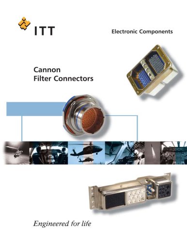 Filter full catalog
48 Pages
 D-Sub Full Line Catalog
302 Pages
 CACOM E
42 Pages
 CA Bayonet V2
68 Pages
 Audio XL
36 Pages
 APD
APD79 Pages


Archived catalogs
 Nemesis Full Line Catalog
44 Pages