
- Catalogs
- ITT Cannon
- CGL Connectors

- Products
- Catalogs
- News & Trends
- Exhibitions
CGL Connectors

CGL Connectors
ITT Corporation is a prominent manufacturer of engineered components and technology solutions, serving markets such as energy, transportation, and industrial sectors. Established in 1920, the company is headquartered in White Plains, NY, and operates in over 35 countries.
ITT's connector portfolio includes brands like Cannon, VEAM, and BIW Connector Systems, offering interconnect solutions for industries such as automotive, oil & gas, aerospace, telecom, and defense.
The CGL series features circular connectors for industrial applications, supporting voltages from 250 to 700 VRMS. These connectors have metal shells and adhere to safety voltage limits.
- Designed for mains power usage (250-700 VRMS).
- Grounding contacts linked to the shell.
- Various backshell or adapter options available.
- Universal Endbell provides shielding and sealing up to IP69k.
- 700 V products are UL certified.
The catalog is divided into sections for CGL 250 V–500 V and CGL 700 V versions, detailing product overviews, ordering references, contact arrangements, and tooling information.
- Contact ratings and resistance for different contact sizes.
- Mechanical features include ambient temperature range, safety provisions, vibration tests, and mating cycles.
- Mounting dimensions and coupling torques for various shell sizes.
Customers can select products using ordering references and contact arrangements. Accessories and tooling can be added, with customization options available upon request.
ITT Cannon's CGL connectors offer reliable and versatile solutions for high-voltage industrial applications, focusing on safety, customization, and compliance with industry standards.
- 90° Plug Class PG CGL08: Designed for heat shrink boots or PG terminations, available with bayonet or threaded coupling. Key dimensions and thread specifications are provided.
- Connectors with Universal Endbell: Specifications for straight plug and 90° versions with bayonet and threaded coupling options.
- Special Versions: Available in 250V-500V and 700V versions, with detailed electrical conditions and material specifications.
- Protective Caps: Available for bayonet and threaded coupling connectors, with part numbers and dimensions.
- Tooling: Includes hydraulic and hand crimping tools, crimp dies, and insertion/extraction tools.
- Part numbers and dimensions for various connector configurations.
- Contact arrangements and permissible operating voltages for special versions.
- Tooling specifications for crimping and contact handling.
For specific applications, refer to detailed part numbers and configurations for compatibility and performance. Contact ITT customer service for assistance.
The document details ITT's range of electrical connectors, including circular, filter, hermetic, fiber optic, D-subminiature, microminiature, rack and panel, and Trident connectors, designed for military, transportation, and harsh environments.
Connectors are made from materials like copper, nickel, and steel, with insulators from plastic, rubber, or glass. Using connectors within specified parameters is crucial to avoid hazards.
Proper wiring and assembly are essential to prevent electric shock and fire hazards. Overheating from incorrect assembly or exceeding product ratings can lead to insulation breakdown and fire risks.
Careful handling is necessary to avoid damage. Damaged products should be rejected, and disposal should prevent toxic fume release.
Connectors with exposed contacts should not be used on the current supply side to prevent electric shock. Proper tools and trained personnel are recommended for assembly and maintenance.
Product specifications may change, and users should refer to the latest data sheets. A limited warranty applies, with liability limited to Cannon's terms.
ITT's Interconnect Solutions operates globally, with facilities in China, Hong Kong, Japan, Germany, Italy, Lebanon, the UK, Mexico, and the USA.
Catalog excerpts

ITT Corporation ITT is a diversified leading manufacturer of highly engineered critical components and customized technology solutions for the energy, transportation and industrial markets. Building on its heritage of innovation, ITT partners with its customers to deliver enduring solutions to the key industries that underpin our modern way of life. Founded in 1920, ITT is headquartered in White Plains, N. Y., with employees in more than 35 countries and sales in a total of approximately 125 countries. The company generated 2014 revenues of $ 2.7 billion. For more information, visit www.itt.com....
Open the catalog to page 2
lndustrial / lnstrumentation Transportation Defense Vehicles Oil & Gas Automotive Commercial & Military Aerospace Our connector portfolio remains the most extensive in the industry, offering a reliable and cost effective range of interconnect solutions Computer, Telecom & Consumer Electronics
Open the catalog to page 3
Introduction to CGL Circular connectors featured by metal shells are usually only good for an operating voltage of 50 Volts. Voltages in access to that are considered to be potentially hazardous for any human body. ITT Cannon already in 1987 took appropriate measures to develop the essential design features to respond to this fact. There was an increasing need for connectors of such nature seen in industrial applications like motors and drives and numerous other options wherever goods or things have to be moved. Usually such applications are featured by the utilization of mains power which often...
Open the catalog to page 4
Dimensions shown in mm | Specifications and dimensions subject to change
Open the catalog to page 5
How to use This catalog is split in several sections that help you to •• get a general overview of all product lines (product overview) •• get all required detail information (dimensions, product details) •• get all required support products (accessories, tooling) The fastest way to find your product of choice is to follow these steps First section: CGL 250 V–500 V (see page 7–20) Select your product using the “ordering reference” Add accessories and tooling as required on the related pages Use the detail pages to better understand the available options and choose the best solution for your needs...
Open the catalog to page 6
Product overview CGL 250 V–500 V MECHANICAL FEATURES ELECTRICAL DATA Contact rating at 20°C (68°F) Contact size (AWG/metric) Rated Current (Amax.) Safety provisions Bayonet coupling: IP 68 acc. to ISO 20653 (1 bar pressure within 16 hours) For air and creepage paths, test and operating voltage see page 10 -11 Vibration test 200 m /s² at 10 – 2000 Hz Mating cycles Current rating min. 500 Separating force per contact The separating force has to be measured acc. to VG 95319 part 2, test no 5.7. using the required test gage. Contact size Separating force Contacts resistance The contact resistance...
Open the catalog to page 7
Product overview CGL 250 V–500 V MECHANICAL FEATURES (continued) MECHANICAL FEATURES (continued) Separating and mating force Mounting holes for box mounting connectors, Style CGL02/CGL02-B Shell size Shell size Coupling torques The allowable coupling torques have to be tested under full bundle conditions of the connectors acc. to VG95319 part 2, Test no. 5.8.2. Shell size Allowable coupling torque Nm Closing and opening Opening CGL-B max. CGL/CGL-B min. Dimensions shown in mm | Specifications and dimensions subject to change
Open the catalog to page 8
Ordering reference Part number explanation Shell type 02 – box mounting receptacle with square flange 08 – plug with 90° adapter Class IN – Universal Endbell (nickel plated) PG – with PG adapter (nickel plated) ME – with metric adapter (nickel plated) A – without endbell (style 02 only) Contact arrangement Contact type P – pin S – socket Performance class A1, C1, D1 – dependent on layout, see page 10 Insulator type L – long insulator = 250 V / 500 V Bayonet coupling (for threaded version: omit indication) Contacts* F80 – crimp contacts Outer cable diameter (Universal Endbell only) Modification...
Open the catalog to page 9
CGL 250 V– 500 V VERSIONS CONTACT ARRANGEMENTS Shell size Contact arrangement Contact number Contact size Grounding contact in cavity Admissible operating voltage (VAC) Examples of available connectors CGL02A10SL-3P-C1L*** * The insulator material is FKM. ***Modification codes please see ordering reference, page 9 Dimensions shown in mm | Specifications and dimensions subject to change
Open the catalog to page 10
CGL 250 V– 500 V VERSIONS CONTACT ARRANGEMENTS LAYOUT SPECIFIC DATA Min. air distance (mm) / mating face Contact arrangement Power-Contact Power-Grounding Signal-Contact Rated Voltage Min. creepage distance (mm) / mating face Contact arrangement Power-Contact Power-Grounding Signal-Contact Rated Voltage Admissible operating voltage The admissible operating voltages indicated in this catalogue are mainly based on customer information for certain projects. The tables above indicate the actual value for the air and creepage distances and can be used as a calculation basis in connection with DIN...
Open the catalog to page 11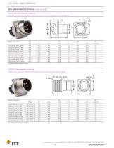
CGL 250 V– 500 V VERSIONS BOX MOUNTING RECEPTACLE CLASS E CGL02 CGL02A-B with bayonet coupling CGL02-B is a box mounting receptacle for front panel mounting. It mates with plugs CGL06-B and CGL08-B For socket inserts substitute P with S CGL02A with threaded coupling CGL02A is a box mounting receptacle for front panel mounting. It mates with plugs CGL06 and CGL08 For socket inserts substitute P with S Dimensions shown in mm | Specifications and dimensions subject to change
Open the catalog to page 12
CGL 250 V– 500 V VERSIONS STRAIGHT PLUG CLASS PG CGL06 CGL06PG/ME-B with bayonet coupling CGL06PG/ME-B designates a straight plug for the use of heat shrink boots or PG terminations (optional a metric adapter is available). It mates with receptacle CGL02A-B Part No. (socket insert) For pin inserts substitute S with P For ME-adapter substitute PG with ME CGL06PG/ME with threaded coupling CGL06PG/ME designates a straight plug for the use of heat shrink boots or PG terminations (optional a metric adapter is available). It mates with receptacle CGL02A. Part No. (socket insert) For pin inserts substitute...
Open the catalog to page 13All ITT Cannon catalogs and technical brochures
 Banding Adapters
2 Pages
 Tin Zinc J Plating
2 Pages
 MDSM Catalog
16 Pages
 Portfolio Catalog
63 Pages
 NEMESIS brochure
4 Pages
 CIR Series
218 Pages
 CIR-M12 Databus Brochure
4 Pages
 CGE Catalog
8 Pages
 Chip-on-Flex Filter Catalog
6 Pages
 Trident Catalog
96 Pages
 Space Connectors Catalog
118 Pages
 DL Series ZIF Connectors Catalog
75 Pages
 PowerLock & SnapLock Catalog
39 Pages
 Rack & Panel Connectors Catalog
120 Pages
 ComboD
103 Pages
 CMX FB
2 Pages
 CFast
CFast4 Pages
 Filter full catalog
48 Pages
 D-Sub Full Line Catalog
302 Pages
 CACOM E
42 Pages
 CA Bayonet V2
68 Pages
 Audio XL
36 Pages
 APD
APD79 Pages


Archived catalogs
 Nemesis Full Line Catalog
44 Pages
- Data connector
- Electrical power supply connector
- Metal connector
- Polymer connector
- Screw-in connector
- Socket electrical connector
- Industrial connector
- IP67 connector
- Rectangular connector
- Male connector
- RF connector
- Copper connector
- DIN connector
- Voltage connector
- Crimp connector
- Multipole connector
- Plug-in connector
- Coaxial connector