
- Catalogs
- ITT Cannon
- CACOM E

- Products
- Catalogs
- News & Trends
- Exhibitions
CACOM E

CACOM E
ITT Industries' Cannon connectors series CA-COM and CA-COM-B are designed for industrial applications, adhering to MIL-C-5015 and VG95234 standards. They offer various mounting options and accessories, ensuring versatility and durability in harsh environments.
The CA-COM series features threaded coupling, while the CA-COM-B series uses bayonet coupling. Both series support solder or crimp contacts, with arrangements ranging from 1 to 37 contacts. They accommodate wire sizes from 0.14 to 2.5 mm² and are constructed from nickel-plated aluminum alloy for high mechanical strain resistance.
Electrical specifications include a rated current of up to 100A, contact resistance as low as 1 mΩ, and insulation resistance over 1000 MΩ. The connectors are designed for a temperature range of -55°C to 125°C and support a minimum of 500 mating cycles. They are resistant to aggressive fluids and waterproof up to 1 bar for 12 hours.
Ordering involves specifying the series, shell style, class, shell size, contact arrangement, contact type, and any modifications. Various configurations are available to meet specific application needs.
Contact arrangements are detailed by shell size, with specific configurations for different service ratings and wire sizes. Alternate insert positions are available to prevent cross-plugging.
Detailed dimensions for mounting, separating, and coupling are provided for different shell sizes and styles, ensuring compatibility and ease of installation.
A range of accessories, including protective caps, cable clamps, and sealing gaskets, are available to enhance the functionality and protection of the connectors. Tools for installation and maintenance are also specified.
Usage guidelines emphasize compliance with safety regulations, particularly when operating at voltages above 50V, to prevent electrical shock during connector mating and unmating.
This document provides technical specifications for various types of connectors and receptacles used in electrical and electronic applications. The connectors are categorized based on their coupling mechanisms, mounting styles, and compatibility with different plug types.
- CA02COM-E: A box mounting receptacle for front panel mounting with threaded coupling. It mates with plugs CA06COM and CA08COM. Dimensions and thread specifications are provided for different part numbers.
- CA20COM-E: Similar to CA02COM-E but designed for rear panel mounting. It also uses threaded coupling and mates with the same plug types.
- CA02COM-L: A box mounting receptacle with threaded coupling for front panel mounting, compatible with CA06COM and CA08COM plugs. It includes detailed dimensions and thread specifications.
- CA20COM-L: Designed for rear panel mounting with threaded coupling, similar to CA02COM-L.
- CA06COM-PG: A straight plug with threaded coupling for PG terminations, compatible with CA00COM, CA01COM, and CA02COM-E receptacles.
- CA06COM-E: A straight plug with threaded coupling, featuring an endbell and cable clamp, compatible with CA00COM, CA01COM, and CA02COM-E receptacles.
- CA06COM-F: A straight plug with threaded coupling and endbell for flex tubes, compatible with CA00COM, CA01COM, and CA02COM-E receptacles.
- CA06COM-E-DN: A straight plug with threaded coupling and endbell for wire sealing, designed for heat shrink boots, compatible with CA00COM, CA01COM, and CA02COM-E receptacles.
- CA06COM-IN: A straight plug with threaded coupling and universal endbell, compatible with CA00COM, CA01COM, and CA02COM-E receptacles.
- For socket inserts, substitute “S” for “P” in the part number.
- Contact arrangement numbers should be added as specified on pages 6-8 of the document.
- Dimensions are provided in millimeters for each part number, detailing parameters such as maximum thread size, cable sealing area, and other critical dimensions.
- Thread specifications follow standard UNEF and UNS thread types, with specific dimensions for each connector type.
- All dimensions are subject to change, and users should verify specifications before use.
- Compatibility with specific plug types is crucial for ensuring proper connection and functionality.
1. Hand Crimp Tool: Dimensions (closed, without locator) are 220 x 60 x 22 mm, and it weighs approximately 800 g without the turret.
2. Pneumatic Crimp Tool: Pneumatic table crimp tool WA 27F-CE.
3. Hydraulic Hand Crimp Tool: Includes a hand pump with dimensions of 560 mm length, 140 mm width, and 120 mm height. The oil content is 900 cm³ with usable oil quality at 730 cm³. The output per lift is 2.5 cm³. The high-pressure hose is 2 m long, and the crimp head has a crimp force of 120 kN and a lift of 25 mm. The total weight, including oil, is approximately 13 kg.
1. Material Content and Physical Form: Electrical connectors are generally non-hazardous, made from conducting and non-conducting materials. They are categorized into printed circuit types and rugged types with metal casings.
2. Fire Characteristics and Electric Shock Hazard: No fire hazard exists if connectors are used correctly. Incorrect use can lead to electric shock or burns. Overheating can occur due to poor connections or exceeding product ratings.
3. Handling: Care is needed to avoid damage during installation and use. Products should be inspected for damage before use.
4. Disposal: Incineration of materials may release toxic fumes.
5. Application: Connectors with exposed contacts should not be used on the current supply side to avoid electric shock. Ensure no damage or undesired conducting particles are present before use.
1. Air and Creepage Paths/Operating Voltage: Operating voltages depend on applications and safety regulations.
2. Temperature: Information provided are temperature limits; actual operation temperature depends on the application.
3. Product Improvements: Cannon products may deviate from catalog descriptions due to continuous improvements.
4. Harnessing and Assembly Instructions: Special instructions are available upon request.
Details for Cannon facilities worldwide, including addresses, phone, and fax numbers, are provided for countries such as Austria, Benelux, China, Denmark, Finland, France, Germany, Hong Kong, Italy, Japan, Korea, Spain, Sweden, Switzerland, United Kingdom, and the United States.
Catalog excerpts


CA-COM Introduction ITT Industries, Cannon connectors series CA-COM and CA-COM-B are derivations of connectors according to MIL-C-5015 or VG95234. They were developed especially for industrial applications. Connectors of both CA-COM series are interchangeable with the corresponding types as per MILC-5015 and VG95234, as they offer the same mounting dimensions and contact arrangements. The CA-COM and CA-COM-B connector series offer • Wall mounting receptacles • Cable connecting plugs • Box mounting receptacles • Straight plugs • Plugs 90° Wall mounting receptacles and cable connecting plugs (straight...
Open the catalog to page 2
CA-COM Electrical data Mechanical data Rated current 20°C ambient temperature Max operating temperature acc. to DIN IEC 68, part 1 –55/125°C Contact size AWG / metric 15S 15 25 100 Mating cycles Min separating force per contact 1 ) This applies only to the max. rated current for one contact. If several contacts in one contact arrangement are loaded with higher current the specific heat and the ambient temperature may not exceed +125°C. Rated current vs. ambient temperature Insulation resistance > 1000 MΩ Air and creepage paths mm (min) Instr. 0,7 0,7 Coupling torque The allowable coupling torque...
Open the catalog to page 3
COM-E COM-E Series CA - Cannon designation Shell style 00 - Wall mount receptacle 01 - Cable connecting plug 02 - Box mount receptacle 20 - Box mount receptacle for rear wall mounting (Bayonett coupling only) 06 - Plug, straight 08 - Plug 90° Class COM-E - Endbell with cable clamp 1) COM-F - Endbell for flex tube COM-PG - Adapter for PG termination, environmental COM-L - PCB Solder termination COM-IN - universal endbell Shell size 10SL, 12S, 14S, 16, 16S, 18, 20, 22, 24, 28, 32*, 36* (* = upon request) Contact arrangement see pages 6 – 8 Contact type P - Pin contact S - Socket contact Alternate...
Open the catalog to page 4
CA-COM Contact arrangements On pages 6 – 8 the contact arrangements are shown by shell sizes. The table below gives an overview on the number of contacts, recommended contact and wire sizes and the service rating class. Other contact arrangements acc. to MIL-C-5015 and VG 95234 upon request. Shell size 10SL 12S 14S Service rating nach IEC A A A Inst. Inst. Inst. Inst. A A A (B, C, F, G) Inst. (all others) A A A A A A A A A A A A D (H) Inst. A Additional contact arrangements (per MIL-C-5015 and VG95234) upon request. Wire selection Contact size Metric 15S 15 25 100 Stripping lengths of wires Strip...
Open the catalog to page 5
Contact Arrangements No. of Contact Service Insulator position Insulator weight (g) contacts arrangement rating W X Y Z including contacts Contact size
Open the catalog to page 6
Contact Arrangements No.of Contact Service Insulator position Insulatorweight(g) contacts arrangement rating W X Y Z including contacts Contact size
Open the catalog to page 7
Contact Arrangements No.of Contact Service Insulator positions Insulatorweight(g) contacts arrangement rating W X Y Z including contacts Contact size
Open the catalog to page 8
Alternate insert positions Alternate insert positions are available to prevent cross-plugging of adjacent con- nectors. The standard position is without designation. All other insert positions are designated W, X, Y and Z. See table below. View on mating face of pin insert
Open the catalog to page 9
Mounting dimensions Mounting holes for connectors styles Shell CA-COM Threaded CA-COM-Bayonet
Open the catalog to page 10
CA-COM Separating and coupling dimensions CA06COM-E CA06COM-E-B CA02COM-E CA02COM-E-B
Open the catalog to page 11
Wall mounting receptacle, Class PG with threaded coupling terminations. It mates with plugs * For socket inserts substitute "S" for "P" ** Add contact arrangement number (see pages 6-8)
Open the catalog to page 12
CA-COM Wall mounting receptacle, Class E CA00COM-E-B with bayonet coupling CA00COM-E-B is a wall mounting receptacle with endbell and cable clamp. It mates with plugs CA06COM-B and CA08COM-B. CA00COM-E with threaded coupling CA00COM-E is a wall mounting receptacle with endbell and cable clamp. It mates with plugs CA06COM and CA08COM. * For socket inserts substitute “S” for “P” ** Add contact arrangement number (see pages 6 – 8) 1 ) max cable dia
Open the catalog to page 13
Wall mounting receptacle, Class F with threaded coupling receptacle with endbell for flex tubes. It mates with plugs For socket inserts substitute "S" for "P" Add contact arrangement number (see pages 6-8)
Open the catalog to page 14
Wall mounting receptacle, Class E with bayonet coupling mounting receptacle (wire sealing) for heat shrink boots. It mates with threaded coupling receptacle with endbell (wire sealing) for heat shrink boots. It mates with * For socket inserts substitute "S" for "P" ** Add contact arrangement number (see pages 6-8)
Open the catalog to page 15
CA-COM Cable connecting plug, Class PG CA01COM-PG-B with bayonet coupling CA01COM-PG-B is a cable connecting plug for usage of PG terminations. It mates with plugs CA06COM-B and CA08COM-B. CA01COM-PG with threaded coupling CA01COM-PG is a cable connecting plug for usage of PG terminations. It mates with plugs CA06COM and CA08COM. * For socket inserts substitute “S” for “P” ** Add contact arrangement number (see pages 6 – 8) All dimensions are in mm Subject to changes
Open the catalog to page 16
CA-COM Cable connecting plug, Class E CA01COM-E-B with bayonet coupling CA01COM-E-B is a cable connecting plug with endbell and cable clamp. It mates with plugs CA06COM-B and CA08COM-B. CA01COM-E with threaded coupling CA01COM-E is a cable connecting plug with endbell and cable clamp. It mates with plugs CA06COM and CA08COM. * For socket inserts substitute “S” for “P” ** Add contact arrangement number (see pages 6 – 8) 1 ) max cable dia
Open the catalog to page 17
Cable connecting plug, Class E with bayonet coupling connecting plug with endbell (wire sealing) for heat shrink boots. It mates with plugs with threaded coupling connecting plug with endbell (wire sealing) for heat shrink boots. It mates with plugs * For socket inserts substitute "S" for "P" ** Add contact arrangement number (see pages 6-8)
Open the catalog to page 18All ITT Cannon catalogs and technical brochures
 Banding Adapters
2 Pages
 Tin Zinc J Plating
2 Pages
 MDSM Catalog
16 Pages
 Portfolio Catalog
63 Pages
 NEMESIS brochure
4 Pages
 CIR Series
218 Pages
 CGL Connectors
28 Pages
 CIR-M12 Databus Brochure
4 Pages
 CGE Catalog
8 Pages
 Chip-on-Flex Filter Catalog
6 Pages
 Trident Catalog
96 Pages
 Space Connectors Catalog
118 Pages
 DL Series ZIF Connectors Catalog
75 Pages
 PowerLock & SnapLock Catalog
39 Pages
 Rack & Panel Connectors Catalog
120 Pages
 ComboD
103 Pages
 CMX FB
2 Pages
 CFast
CFast4 Pages
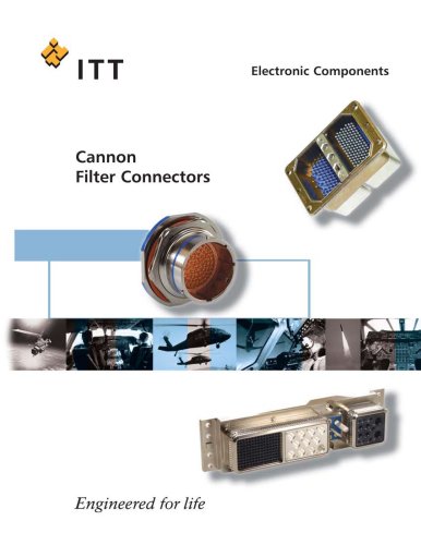 Filter full catalog
48 Pages
 D-Sub Full Line Catalog
302 Pages
 CA Bayonet V2
68 Pages
 Audio XL
36 Pages
 APD
APD79 Pages


Archived catalogs
 Nemesis Full Line Catalog
44 Pages
- Data connector
- Electrical power supply connector
- Metal connector
- Circular connector
- Polymer connector
- Screw-in connector
- Socket electrical connector
- IP67 connector
- Rectangular connector
- Male connector
- RF connector
- Copper connector
- DIN connector
- Voltage connector
- Crimp connector
- Multipole connector
- Plug-in connector
- Coaxial connector