- Catalogs
- ITG Linear Motor
- ITC Linear Iron Core
ITC Linear Iron Core
1 /62Pages
ITC Linear Iron Core
1 /62Pages
Catalog excerpts
IRONCORE LINEAR MOTOR MANUAL Simply Better !
Open the catalog to page 1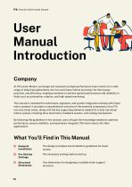
ITG Ironcore linear motor manual User Manual Introduction Company At ITG Linear Motors, we design and manufacture high-performance linear motors for a wide range of industrial applications. Our iron core linear motors are known for their power, precision, and efficiency, enabling machines to achieve optimal performance and reliability in fields such as automation, robotics, and high-speed machining. This manual is intended for technicians, engineers, and system integrators working with linear motor systems. It provides a comprehensive overview of the essential components of an ITG iron core linear...
Open the catalog to page 2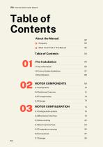
ITG Ironcore linear motor manual What You’ll Find in This Manual 1.2 Critical Safety Guidelines
Open the catalog to page 3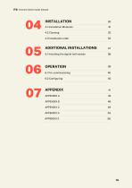
ITG Ironcore linear motor manual 5.1 Installing the digital hall module 38
Open the catalog to page 4
ITG Ironcore linear motor manual
Open the catalog to page 5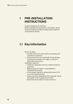
ITG Ironcore linear motor manual 1 PRE-INSTALLATION INSTRUCTIONSEssential Guidelines for Safe UseBefore installing and operating the Linear Motor, please read the following carefully to ensure proper setup and avoid potential hazards.1.1 Key Information Before You Begin • Carefully review this manual before proceeding with installation or operation. • The manufacturer is not responsible for any damage resulting from improper use, neglect, or failure to follow these instructions. Handling & Inspection • Handle all components with care, whether packed or unpacked. • Magnet plates are fragile —...
Open the catalog to page 6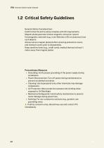
ITG Ironcore linear motor manual General Safety Considerations Confirm that the entire setup complies with CE requirements. Magnet plates generate intense magnetic attraction toward ferromagnetic materials (e.g., iron). Maintain a 25 cm clearance from such objects. Always secure magnet plates before removing protective covers, and reattach covers prior to disassembly. Keep sensitive items (e.g., credit cards, medical devices) at least 1 meter away from magnet plates. Precautionary Measures • Grounding: Verify proper grounding of the power supply during installation. • Power Disconnection: Turn...
Open the catalog to page 7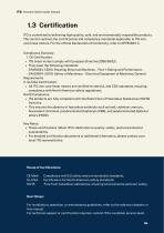
ITG Ironcore linear motor manual ITG is committed to delivering high-quality, safe, and environmentally responsible products. This section outlines the certifications and compliance standards applicable to ITG iron-core linear motors. For the official Declaration of Conformity, refer to APPENDIX C. Compliance Overview • ITG linear motors comply with European Directive 2006/95/EC. • They meet the following standards: - EN 60034-1:2010: Rotating Electrical Machines - Part 1: Rating and Performance. - EN 60204-1:2010: Safety of Machinery - Electrical Equipment of Machines: General • All ITG iron-core...
Open the catalog to page 8
ITG Ironcore linear motor manual MOTOR COMPONENTS
Open the catalog to page 9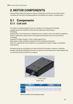
ITG Ironcore linear motor manual 2. MOTOR COMPONENTS This section provides an overview of the key components of ITG iron-core linear motors, including their features, handling guidelines, and application-specific considerations. IITG offers a versatile range of coil units, available in N-winding and S-winding configurations, each tailored to meet specific application requirements: N-Winding: Optimized for current efficiency, enabling the use of smaller, more cost-effective amplifiers. Ideal for applications where power consumption and amplifier size are critical factors. S-Winding: Designed for...
Open the catalog to page 10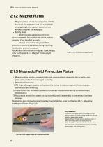
ITG Ironcore linear motor manual 2.1.2 Magnet Plates Magnet plates are a core component of ITG iron-core linear motors and are available in varying lengths to support optimized and efficient magnet track designs. Safety Note: - Magnet plates generate extremely strong magnetic forces that can cause serious jamming if not handled properly. - Always ensure that magnetic field protection covers are in place during handling, installation, and maintenance. For detailed information on magnet track design, refer to Chapter 3.1.1 – Magnet Track Length (Page 15). Picture 2.4: A IC76192mm magnet plate 2.1.3...
Open the catalog to page 11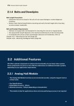
ITG Ironcore linear motor manual Bolt Length Precautions: • Using bolts that are too long for the coil unit can cause damage or create dangerous situations. • Always check the bolt length before mounting and verify the bolt height after mounting to ensure proper installation. Bolt and Dowelpin Requirements: • ITG does not supply bolts and dowelpins for mounting the coil unit or magnet plates. • The required bolt length depends on the mechanical dimensions of the mounting slide. • For detailed instructions on bolt and dowelpin selection and installation, refer to: Chapter 4.3.1 - Mounting the...
Open the catalog to page 12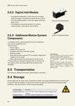
ITG Ironcore linear motor manual Bolts and Dowelpins: Ensure proper bolt length and height to avoid damage or safety risks. Analog Hall Module: A cost-effective alternative for incremental encoding with moderate accuracy. Digital Hall Module: Enables commutation in systems without integrated servo drive support. Additional Components: A complete motion system requires external components not supplied by ITG. 2.2.2 Digital Hall Module • The Digital Hall Module is used when the controller does not support commutation within the servo drive. • Like the analog module, it uses the magnet track as...
Open the catalog to page 13
ITG Ironcore linear motor manual MOTOR CONFIGURATION
Open the catalog to page 14
ITG Ironcore linear motor manual Individual iron core coils can be paired together. This can be achieved on two separate magnet tracks for gantry-style applications or on a single magnet track to generate greater force. The latter option is particularly advantageous for reducing costs in long-stroke applications. By coupling two coils, a smaller series coil and magnet track can be utilized, which helps lower the overall cost of the magnet track. Magnet length calculation with coil unit length Hr = Required stroke 440mm Lc = IC76-6 Coil unit length 146mm Mpl = Magnet plate length 288mm Required...
Open the catalog to page 15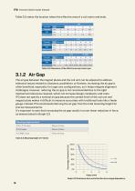
ITG Ironcore linear motor manual Table 3.2 states the location where the effective area of a coil starts and ends. The air gap between the magnet plates and the coil unit can be adjusted to address tolerance issues related to clearance, parallelism, or flatness. Increasing the air gap is often beneficial, especially for large-axis configurations, as it helps mitigate alignment challenges. However, reducing the air gap is not recommended due to the tight mechanical tolerances required, which can increase design complexity and costs. ITG does not specify a nominal air gap because the casted finish...
Open the catalog to page 16All ITG Linear Motor catalogs and technical brochures
 ITG Linear Ironless Manual 2025
37 Pages
 ITG Linear Motor
38 Pages
- Position transducer
- Linear position transmitter
- Analog position transducer
- Absolute position sensor
- Torque motor
- Synchronous torque motor
- Performance torque motor
- Digital position sensor
- High-speed linear motor
- Synchronous linear motor
- Compact linear motor
- Multipole torque motor
- Three-phase linear motor
- High-torque torque motor
- Ironless linear motor
- Machine tool torque motor
- Hall effect position sensor