- Catalogs
- ISOIL Industria Spa
- ISOMAG MS 501
- Company
- Products
- Catalogs
- News & Trends
- Exhibitions
ISOMAG MS 501
1 /14Pages

ISOMAG MS 501
1 /14Pages
Catalog excerpts

MICROFLOW SENSOR WITH A WIDE RANGE OF APPLICATIONS THANKS TO THE AVAILABILITY OF DIFFERENT CONNECTION The manufacturer guarantees only English text. Available on our web site: www.isomaq.eu The solutions that count
Open the catalog to page 1
The Manufacturer Guarantee Only English Text Available on our web site: www.isoil.com
Open the catalog to page 2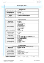
TECHNICAL DATA OVERALL FEATURES Nominal diameter Minimum conductivity Humidity Range See relevant converter data sheet STANDARD FEATURES Body material Nominal pressure Process connections Threaded UNI 338 Threaded NTP Flanged UNI 2278 Flanged ANSI 150 Sanitary DIN 11851 Clamp ISO 2852 Clamp BS 4825 SMS Version – protection rating Connections material Lining material Gasket material Liquid temperature -20°C ÷ 100°C comp. (130°C only with ML4F-1) -20°C ÷ 130°C separate Vacuum resistance Electrodes material AISI 316L Hastelloy C Platinum – rhodium Titanium Tantalum OPTIONAL FEATURES (CHECK FOR MORE...
Open the catalog to page 3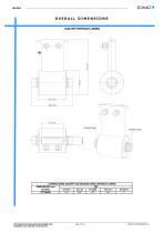
OVERALL DIMENSIONS GAS/NPT WITHOUT LINING The Manufacturer Guarantee Only English Text Available on our web site: www.isoil.com
Open the catalog to page 4
GAS/NPT WITH LINING The Manufacturer Guarantee Only English Text Available on our web site: www.isoil.com
Open the catalog to page 5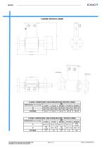
FLANGED WITHOUT LINING CONNECTIONS CONNECTIONS The Manufacturer Guarantee Only English Text Available on our web site: www.isoil.com
Open the catalog to page 6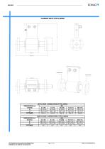
FLANGED WITH PTFE LINING CONNECTIONS CONNECTIONS DIMENSIONS mm (inches) D H FITTINGS DIMENSIONS mm (inches) D H FITTINGS The Manufacturer Guarantee Only English Text Available on our web site: www.isoil.com
Open the catalog to page 7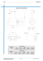
SANITARY CLAMP CONNECTIONS CLAMP ISO 2852 DIMENSIONS mm (inches) I F CLAMP BS 4825 DIMENSIONS mm (inches) I F The Manufacturer Guarantee Only English Text Available on our web site: www.isoil.com
Open the catalog to page 8
SANITARY DIN/SMS The Manufacturer Guarantee Only English Text Available on our web site: www.isoil.com
Open the catalog to page 9
INSTALLATION RECOMMENDATIONS In vertical installations an ascending flow is preferable. For vertical installations with descending flow direction contact the manufacturer For installations in long pipe lines, please use anti vibration joints LONG PIPING Avoid a partially empty pipe, during operation the pipe must be either completely full of liquid or completely empty Install the sensor away from bends and hydraulic accessoriesds and hydraulic accessories Avoid positioning flange and counter flanges by tigthening the nuts. SENSOR'S FITTING The Manufacturer Guarantee Only English Text Available...
Open the catalog to page 10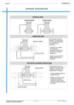
SENSOR GROUNDING METALLIC PIPE THREADED SENSOR FLANGED SENSOR INSULATED PIPE SEALING GASKET METALLIC RING If the sensor has to be installed in a pipe made of an insulating material, the following are necessary: - Inserting two metallic rings between the sensor flanges and the pipe line counter flanges or: - Using a sensor with the additional grounding electrode PIPE WITH CATHODIC PROTECTION SEALING GASKET If the sensor has to be installed in the pipe with a cathodic protection, the following are necessary: - using insulating bushes to isolate the bolts - Metallic grounding rings should be provided...
Open the catalog to page 11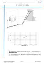
SEPARATE VERSION CONDUCTIVITY (µS/cm) It is recommended to install the connection cables away from, or protect against sources of electromagnetic noise. The minimum conductivity of the liquid medium to ensure correct functionality of the empty pipe detection is 20 µS/cm The Manufacturer Guarantee Only English Text Available on our web site: www.isoil.com
Open the catalog to page 12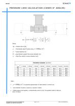
PRESSURE LOSS CALCULATION (CONES 8° ANGLES) = Fluid density [kg/m3] typical value = pipe diameter (greater than sensor diameter) [m] = Mean flow velocity in sensor diameter [m/s] Calculation examples Inner diameter of sensor is used for d, express in meters. as goodness approximation of water density in common use. Indeed pressure loss equation is dimensionally correct in [Pa]. The equation results in table are show in [mbar].
Open the catalog to page 13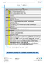
Nominal Diameter / Lining / Maximum temperature / Measuring range T03 T06 T10 T15 T20 DN3 ( 1/8 "), PTFE lining, measuring range 0.. 10,4 / 0...259 l/h DN6 ( 1/4 "), PTFE lining, measuring range 0...41,4/0...1036 l/h DN10 (3/8 "), PTFE lining, measuring range 0..115.2/0...2880 l/h DN15 (1/2 "), PTFE lining, measuring range 0.. 259.2/0...6480 l/h DN20 (3/4 "), PTFE lining, measuring range 0.. 460.8/0...11520 l/h Gasket material ( internal tightness ) 1 O-Ring : FKM O-Ring : Epdm O-Ring : FFKM Gasket material: to be specified Nominal pressure: PN16 Nominal pressure: PN40 Nominal pressure: others...
Open the catalog to page 14All ISOIL Industria Spa catalogs and technical brochures
 MS600
MS60010 Pages
 Data Logger MV155
2 Pages
 ISOMAG Magnetic flowmeters
8 Pages
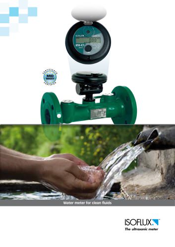
 ISOFLUX IFX serie 04
51 Pages
 ISOMAG MS1000
12 Pages
 ISOMAG MS2410
10 Pages
 ISOFLUX IFX serie 03
22 Pages
 ISOMAG MS 1000
12 Pages
 ISOMAG MS 5000
9 Pages
 ISOMAG MS 3900
11 Pages
 ISOFLUX IFX-P210
6 Pages
 ISONRG DMT
6 Pages
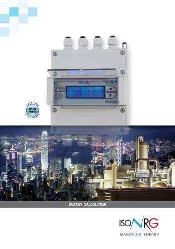 ISONRG ML311
4 Pages
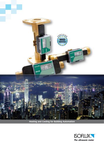
 ISOFLUX Heat meter IFX-E3
4 Pages
 ISONRG_Brochure
4 Pages
 The ISOFLUX Line
4 Pages


- Valve
- Flowmeter
- Water valve
- Ball valve
- Temperature probe
- Volume flow monitor
- Liquid flow monitor
- Regulating valve
- Automation software solution
- Management software solution
- Data logger
- Resistance temperature sensor
- Electric valve
- Analysis software solution
- Process software
- Real-time software
- Waterproof flow meter
- Control software
- Temperature datalogger
- Stainless steel flow monitor