- Catalogs
- ISOIL Industria Spa
- ISOFLUX IFX serie 04
- Company
- Products
- Catalogs
- News & Trends
- Exhibitions
ISOFLUX IFX serie 04
1 /51Pages

ISOFLUX IFX serie 04
1 /51Pages
Catalog excerpts

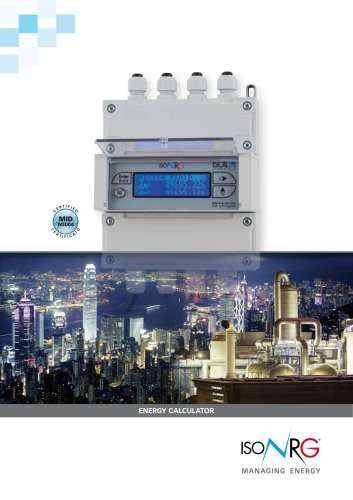
ULTRASONIC HEAT METER IFX-M4-04 TECHNICAL DESCRIPTION
Open the catalog to page 1
SAFETY REQUIREMENTS Before operating the meter, please read this technical description and user's manual thoroughly and follow their instructions. When the meter is powered from the battery (3.6 V), risk factors during the meter installation and service is a heat conveying fluid with inner pressure up to 1,6 MPa and temperature up to 1800C. If meter is powered from mains power supply, it contains dangerous ~230 V electrical current. It is necessary to follow general safety requirements during installation and maintenance process. To eliminate this risk, only qualified technical personnel...
Open the catalog to page 2
For EU Customers only - WEEE Marking. Marking of electrical and electronic equipment in accordance with Article 11 (2) of Directive 2002/96/EC This symbol on the product indicates that it will not be treated as household waste. It must be handed over to the applicable take-back scheme for the recycling of electrical and electronic equipment. For more detailed information about the recycling of this product, please contact your local municipal office.
Open the catalog to page 3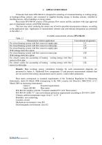
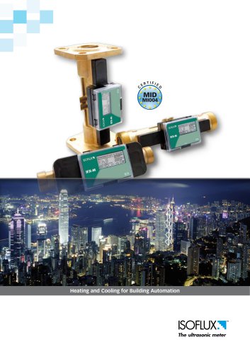
1. APPLICATION FIELD Ultrasonic heat meter IFX-M4-04 is designed for metering of consumed heating or cooling.energy in heating/cooling systems, and consumed or supplied heating energy in heating systems, installed in dwelling houses, office buildings or energy plants. Heat meter IFX-M4-04 consists of the primary flow sensor and the calculator with type approved pair of temperature sensors with Pt500 elements. The user may select (ordering the meter) one of twelve possible measurement schemes, according to the application type. Application of measurement schemes and conventional designation are...
Open the catalog to page 4
Type number combination of the heat meter IFX-M4-04 for order placing: Type The flow sensor installation: In flow pipe In return pipe Destination of the heat meter: For measuring heating energy For measuring heating and cooling energy Flow sensor: Permanent flow rate, m3/h 3.5 6 10 15 25 40 60 Supply Power: Internal Lithium battery External supply power 230 VAC Communication module: None M-bus module RS232 module Universal module (RS232/M-bus/CL ant Current outputs) Wireless Radio readout module RF 868 MHz Length of sensors connection cable, m : 3m 5m 10 m 15 m 20 m 40 m 60 m 80 m 100 m Communication...
Open the catalog to page 5
2. TECHNICAL DATA 2.1. Energy measurement 2.1.1. Accuracy class - 2 Maximum permissible heat energy measurement error of calculator and flow sensor: E (2,5 min / 0,02q p / q), %; Maximum permissible heat energy measurement error of complete meter (error of temperature sensors pair included): E = (3+4 min /Θ +0,02qp/ q) where: min - lower limit of the ntemperature difference, K; - temperature difference, between the measured flow and return temperatures of heat-conveying liquid K; - permanent flow-rate, m³/h ; qp - measured flow-rate, m³/h . q 2.1.2. Thermal energy calculation...
Open the catalog to page 6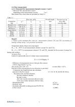
2.3. Flow measurement 2.3.1. Ultrasonic flow measurement channels (sensors) 1 and 2 - Ultrasonic flow measurement sensors (depending on the measurement circuits) 2 or 1 Heat meater flow sensor data are presented in Table 2.1 Table 2.1 Connection type Thread G 1¼ Thread G 1¼ Thread G 2 Flange DN50 DN65 DN80 DN100 Pressure loss p, at qp, kPa, not more than 4 10 10 12 20 18 18
Open the catalog to page 7
2.3.2. Flow pulse input ( 3 and 4) - number of pulse inputs 2 - pulse input device class IB (or IC,if the noise filtrer is Off) - pulse values programmable - type of pulses active, passive - high voltage ranges of active pulses 2,5...3,7V - low voltage ranges of active pulses 0 ...0,7V - input resistance* at the bartery supply 2 MOm - input resistance* at the main supply 10 kOm (*Resistance of internal resistor to 3.6 V circuit) - integrated programmable filter: programmatically rejected input pulses, where the repetition period 2...999 ms is less than the stated period of the filter (only for...
Open the catalog to page 8
2.4. Pressure measurement - Number of pressure inputs - Display units - Fiducial error 0...2 kPa not more than 0,25 of the upper limit of the measurement range Pressure measurement ranges: - lower limit , programmable - upper limit, programmable Normalized input dimension from 0 kPa to 2500 kPa from 100 kPa to 2500 kPa current, linearly dependent on the pressure 0-5 mA, 0-20 mA, 4-20 mA 110 Om - input current limits, programmable - input resistance 2.5. Time measurement Relative time measurement error not more than 0,01 % Heat meter calculator measures: - real time - calendar - time, when...
Open the catalog to page 9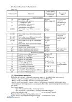
2.7. Measured and recorded parameters: Table 2.4 Arbitrary symbol Display capacity, measurement units, measurement ranges Integral parameters Total consumed energy (in accordance with Annex A) 1st component of energy (in accordance with Annex A) 2nd component of energy (in accordance with Annex A) Fluid volume (mass) of 1-st measurement channel Fluid volume (mass) of 2-nd measurement channel Fluid volume (mass) difference between 1-st and 2-nd measurement channels Fluid volume (mass) of 3-rd measurement channel Fluid volume of 4-th measurement channel Total operation time Operation time in normal...
Open the catalog to page 10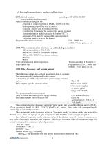
2.9. External communication modules and interfaces 2.9.1. Optical interface according to EN 62056-21:2003 (integrated into the front panel) Optical interface is designed for: - read out of values by protocol EN IEC 62056 or M-bus - direct printing reports (by ASCII codes) - read out archive data by protocol M-bus - configuring of the meter by means of the special protocol (parameterization mode is actuated by button “SET”) - adjusting of the meter by means of the special protocol (adjusting mode is actuated by jumper) Programmable data transfer rate (300 ... 9600) bps with the "Even" parity or...
Open the catalog to page 11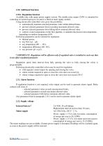
2.10. Additional functions 2.10.1. Regulation function Available only with mains power supply version. The double relay output (230V) is intended for controling of current load up to 2A and it is fitted in main supply module. Using electrically-controlled valve gives the possibility: automatically maintain selected parameter value within defined limits, prevent selected parameter from exceeding maximum allowed value, prevent selected parameter from falling below minimal allowed value control a water temperature on the flow pipeline, to maintain the preset room temperature, depending on...
Open the catalog to page 12All ISOIL Industria Spa catalogs and technical brochures
 MS600
MS60010 Pages
 Data Logger MV155
2 Pages
 ISOMAG Magnetic flowmeters
8 Pages
 ISOMAG MS1000
12 Pages
 ISOMAG MS2410
10 Pages
 ISOFLUX IFX serie 03
22 Pages
 ISOMAG MS 501
14 Pages
 ISOMAG MS 1000
12 Pages
 ISOMAG MS 5000
9 Pages
 ISOMAG MS 3900
11 Pages
 ISOFLUX IFX-P210
6 Pages
 ISONRG DMT
6 Pages
 ISONRG ML311
4 Pages
 ISOFLUX Heat meter IFX-E3
4 Pages
 ISONRG_Brochure
4 Pages
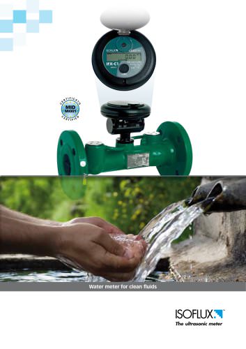 The ISOFLUX Line
4 Pages


- ISOIL flow meter
- Water valve
- Ball valve
- ISOIL volume flow meter
- ISOIL liquid flow meter
- Regulating valve
- Management software solution
- Automation software solution
- Data logger
- Resistance temperature sensor
- Electric valve
- Analysis software solution
- Process software
- Real-time software
- ISOIL waterproof flow meter
- Control software
- Temperature datalogger
- ISOIL stainless steel flow meter