
- Catalogs
- Iskra d.d.
- Radio Interference Suppression Components


Radio Interference Suppression Components

Radio Interference Suppression Components
Radio interference is caused by devices emitting RF energy or rapid electrical current variations. Suppression involves reducing interference at the source or preventing its spread using capacitors, chokes, and filters.
Interference must be limited to ensure proper equipment operation. Measurements are taken up to 30 MHz for interference voltages and above 30 MHz for radiated field strength, following standards like CISPR Publ.11 and EN 55011.
Suppression components are connected to power source terminals or interference sources. Capacitors, chokes, and filter sets are used to suppress interference.
Standards for capacitors and filters include IEC60384-14 and UL1414. Class X capacitors are for non-shock applications, while Class Y capacitors prevent dangerous shocks. Capacitors are rated by voltage, frequency, and capacitance.
Class X and Y capacitors are categorized by peak pulse voltage and insulation type. Rated voltage, frequency, and current are specified for capacitors. Insertion loss and resonant frequency are key characteristics.
Capacitors are for AC applications and should not be used in humid environments. Iskra disclaims liability for misuse of products.
Orders should specify capacitor type, capacitance, voltage, and other requirements. Examples of ordering formats are provided.
- Construction: Made from polypropylene film, metallized, with thermoplastic casing sealed with synthetic resin. The materials are self-extinguishing according to UL 94, class V-0.
- Rated Voltage: Ranges from 250 V AC to 440 V AC, depending on the capacitor type.
- Capacitance Tolerance: ±20% for C ≤ 0.1 μF and ±10% for C > 0.1 μF.
- Climatic Category: Varies by type, generally 40/125/56 or 40/100/56 according to IEC 60068-1.
- Temperature Range: -40 °C to +125 °C for some models, and -40 °C to +100 °C for others.
- Test Voltage: Up to 4000 V D.C. for 1 second, depending on the model.
- Insulation Resistance: Ri ≥ 15000 MΩ for C ≤ 0.33 μF, Ri × Cn ≥ 5000 s for C > 0.33 μF.
- Compliance: Meets standards such as IEC 60384-14, EN 60384-14, UL 1283, UL 1414, CSA C22.2 No.1, and GB/T 14472-1998.
- Soldering: Complies with IEC 60068-2-20, with a maximum soldering time of 5 seconds at 270 °C.
- Electrical Connection: Available in custom design versions, recommended for serial connection.
- Pulse Rise Time: Varies by model, with specific du/dt values provided for different PCM sizes.
- Dielectric Loss: Specified as tanδ ≤ 1 × 10⁻³ at f = 1 kHz and 20 °C for some models.
- Self Inductance: Approximately 10 nH/cm of capacitor length and terminals.
- The document outlines various types of capacitors, including KNB, KPB, and KPR series, with different voltage ratings (275 V AC, 310 V AC, 440 V AC) and capacitance values ranging from 0.0022 μF to 2.2 μF.
- Capacitors are constructed using polypropylene film or paper impregnated with aluminium foil.
- Capacitance tolerance is generally ± 20%, with some variations for specific capacitance values.
- Climatic categories are specified according to IEC 60068-1, with temperature ranges from -40°C to +110°C.
- Capacitors comply with standards such as IEC 60384-14, EN 60384-14, UL 1283, and CSA C22.2 No.8.
- Test voltages for X1 and Y2 capacitors are specified, with X1 capacitors tested at 1790 V D.C. and Y2 capacitors at 2050 V A.C.
- Insulation resistance and dielectric loss are detailed, with specific values for different capacitance ranges.
- Soldering guidelines are provided, with a maximum soldering time of 5 seconds at 270°C.
- Capacitors are designed to be flame retardant, complying with UL 94 class V-0 standards.
- Electrical connections and terminal types are specified for each capacitor series, with options for insulated stranded wire or solid wire.
- Approvals are indicated for each capacitor type, with some approvals pending.
- Capacitors are marked with standard values and approvals in use or pending, denoted by symbols.
- Tables provide detailed dimensions and capacitance values for each capacitor type, along with their compliance with various standards.
- Pulse rise time and insulation resistance values are specified for different physical configurations (PCM values).
The document provides detailed specifications for various capacitor models, including types KPB7325, KPB7341, KPB7426, KPB83xx, KPL3008, KPL3009, and KPL3023. These capacitors are designed for radio interference suppression and comply with standards such as IEC 60384-14, EN 60384-14, CSA C22.2 No.8, and UL 1283.
Capacitor Details:
- Dielectric: Paper impregnated
- Electrodes: Aluminium foil
- Rated Voltage: 275 V A.C.
- Capacitance Tolerance: ± 20%
- Temperature Range: -25°C to +100°C
- Test Voltage: X1 capacitor 1790 V D.C., Y2 capacitor 2050 V A.C.
- Insulation Resistance: Ri ≥ 6000 MΩ
Capacitance and Dimensions:
The document lists various capacitance values for class X1 (μF) and class Y2 (pF) along with their dimensions (d x l in mm). These values vary across different models and configurations.
Electrical Connections:
- Terminals: Fast-on connectors, insulated stranded wire, or solid wire options available.
- Electrical connection resistance: R = 470 kΩ ÷ 2.7 MΩ on request.
Compliance and Approvals:
The capacitors comply with multiple international standards and are approved for use in various climatic categories. Approvals are indicated with symbols in the document.
Additional Notes:
- Other capacitance values are available upon request.
- The document includes detailed tables listing standard values for each capacitor type, including capacitance, inductance, and dimensions.
The document outlines the specifications for various capacitors used in radio interference suppression. The capacitors are classified under different types such as KPL3523, KPL3524, KPL3300, KPL305x, and KPL3350, each with specific rated values for capacitance, inductance, and dimensions.
Capacitance and Inductance:
The capacitors have a rated voltage of 250 V A.C. and 275 V A.C., with capacitance tolerance of ±20% and inductance tolerance ranging from -30% to +50%. The nominal capacitance values vary, with combinations like 0.47μF + 2×4700pF and 1μF + 2×2200pF being common.
Test and Compliance:
The capacitors are tested at voltages such as 1790 V D.C. for X1 capacitors and 3000 V A.C. for Y2 capacitors. They comply with standards like IEC 60939-2, EN 60939-2, UL1283, and CSA C22.2 No.8.
Construction and Materials:
The capacitors are constructed using paper impregnated dielectric and aluminum foil electrodes. They are housed in thermoplastic or aluminum casings, sealed with synthetic resin, and are flame retardant.
Approvals and Usage:
The document indicates approvals in use and pending for various configurations, denoted by symbols. The capacitors are designed for use in environments with a temperature range of -25°C to +85°C.
Applications:
These capacitors are primarily used for radio interference suppression in electrical circuits, ensuring compliance with international standards for safety and performance.
Catalog excerpts
Electrotechnical components Radio Interference Suppression Components
Open the catalog to page 1
General information on Iskra Capacitors for Radio Interference Suppression Components Type Construction of capacitors Class Page KNB metallized polypropylene film capacitor X2 10 KNR metallized polypropylene film capacitor with X2 24 KNB metallized polypropylene film capacitor Y2 26 KNB metallized polypropylene film capacitor Y1 28 KNB metallized polypropylene film capacitor X1 30 KNB metallized polypropylene film capacitor X2Y2 34 KPB impregnated paper capacitor X1 35 KPR impregnated paper capacitor with resistor X1 37 KPB impregnated paper capacitor Y2 38 KPB impregnated paper capacitor X1Y2...
Open the catalog to page 3
General information 1. rigin and spreading O of interference There are two main sources of radio interference: - devices, which due to their construction produce RF energy. These include generators for use in industry, medicine and science, as well as oscillators, radio and TV receivers etc. - devices, which produce a wide spectrum of frequencies due to rapid variations in electrical current intensity. These include devices with switching components, thyristors, triacs, commutators and similar. Interference from source to receiver is spread in three ways: along conductors, by coupling and by...
Open the catalog to page 4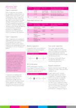
Definitions Taken From Standards: Class X capacitors Class X capacitors are suitable for applications where there is no danger of electrical shock in case of breakdown. Class X capacitors are divided into three subclasses (see table 1) according to the peak voltages of the pulses to which they are exposed during operation in addition to the line voltage. Such impulses can be caused by lightning in overhead lines, switching operations in neighbouring equipment or in the equipment which is shielded by the capacitor. Peak pulse voltage in service Peak value of the surge voltage to be added before...
Open the catalog to page 5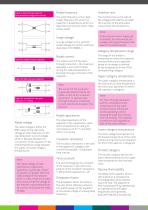
Figure 4: feed through capacitor for symmetrical usage (non-coaxial) Rated frequency Insertion loss The rated frequency is the rated supply frequency for which the capacitor is designed, by which it is described and to which other rated values relate. The insertion loss is the ratio of the voltages both before and after the insertion of the attenuator measured at the connections. Surge voltage A surge voltage is an a-periodic single voltage of a certain profile as described in IEC 60060-1. Figure 5a: single by-pass capacitor Figure 5b: delta by-pass capacitor Figure 5c: example for a by-pass...
Open the catalog to page 6
incorporating the capacitor inparallel with the interference source, interferences are more or less short circuited. A capacitor incorporated in-parallel with power source terminal, suppresses symmetrical interferences, and between a power conductor terminal and the casing or earth it suppresses asymmetrical interferences. Impedance theoretically drops linearly with frequency. Due to shield inductance of the capacitor the capacitor has its own resonant frequency. Above this frequency the capacitor is no self-suppressing component for interference. The value of frequency is decidedly influenced...
Open the catalog to page 7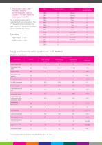
7. roduction date code P marking system according to IEC 60062, clause 5.1 Two-character code (year/month) The production date code is indicated with two-characters. The 1st character (letter) indicates the year and the 2nd character (number/ letter) indicates the month. Taping specification for radial capacitors acc. to IEC 60286-2 (Robotic insertion) Dimensions (mm) Descriptions Carrier tape width Hold-down tape width Hotel position Hold-down tape position Feed hole diameter Feed hole pitch Feed hole centre to lead Feed hole centre to component centre Height from feed hole centre to the component...
Open the catalog to page 8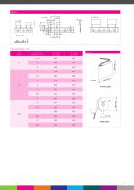
Taped package units Ammo pack Reel pack
Open the catalog to page 9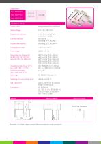
Capacitors Type KNB1530 Type KNB1532 Type KNB1533 TECHNICAL DATA Construction: polypropylene film, metallized Rated voltage: Capacitance tolerance: Climatic category: Passive flammability: Temperature range: Test voltage: Max. pulse rise time du/dt, at 390 V D.C. for 275 V A.C. and 425 V D.C. for 300 V A.C.: Dielectric loss tanδ at f = 1 kHz and 20 °C: Soldering time on printed circuit: Self inductance: approx. 10 nH/cm of capacitor length and terminals Available in custom design version. Recommended for serial connection. Electrical connection
Open the catalog to page 10
ø 0.6 mm for PCM = 10 mm ø 0.8 mm for PCM > 10 mm Casing: thermoplastic, (PP or on request PBT HF) sealed with synthetical resin Thermoplastic material is self-extinguishing according to UL 94, class V-0. Terminals Type Terminal length Tinned copper wire Insulated stranded wire 0.5 mm2 Insulated solid wire ø 0,8 mm End terminals on request Standard values KNB1530, KNB1532, KNB1533, 275 V AC, class X2 For capacitors with insulated leads on request * mini size marking with Approvals in use = • Approvals in pending = o Note: KNB1532 and KNB1533 with PCM = 10 mm are not available with VDE-ENEC.
Open the catalog to page 11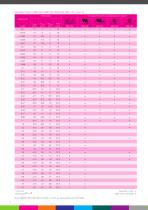
Standard values KNB1530, KNB1532, KNB1533, 300 V AC, class X2 For capacitors with insulated leads on request * mini size marking with Note: KNB1532 and KNB1533 with PCM = 10 mm are not available with VDE-ENEC. 12 Approvals in use = • Approvals in pending = o
Open the catalog to page 12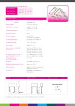
Capacitors with discharge resistor Type KNB1530 Type KNB1532 Type KNB1533 TECHNICAL DATA Construction: capacitor: - resistor: polypropylene film, metallized metaloxide film Rated voltage: Capacitance tolerance: Resistance tolerance: Resistance power: Climatic category: Passive flammability: Temperature range: Test voltage: Max. pulse rise time du/dt, at 425 V D.C.: Dielectric loss tanδ at f = 1 kHz and 20 °C: Soldering time on printed circuit: Self inductance: approx. 10 nH/cm of capacitor length and terminals Electrical connection Available in custom design version. Recommended for serial connection....
Open the catalog to page 13
Casing: thermoplastic. (PP or on request PBT HF) sealed with synthetical resin Thermoplastic material and synthetical resin are self-extinguishing according to UL 94. class V-0. Terminals Type Terminal length Tinned copper wire Insulated stranded wire 0.5 mm2 Insulated solid wire ø 0.8 mm End terminals on request Standard values KNB1530, KNB1532, KNB1533, 275 V AC, class X2, with discharge resistor Dimensions Capacitance C (µF) Resistance values according to IEC 60063 range E12. Approvals in use = • Approvals in pending = o Standard values KNB1530, KNB1532, KNB1533, 300 V AC, class X2, with discharge...
Open the catalog to page 14All Iskra d.d. catalogs and technical brochures
 POWER ELECTRONIC CAPACITORS
51 Pages
 Strip Wound Cores
20 Pages
 Professional Batteries
4 Pages
 General Sales Conditions
4 Pages
 SparkWave SDR GE
2 Pages
 SparkWave High Speed PDH
2 Pages
 SparkWave SDR ADM
2 Pages
 SparkWave SDR STM
2 Pages
 SparkWave SDR GE2
2 Pages
 SparkLight ADM 16
2 Pages
 SparkLight ADM 1,4
2 Pages
 SparkLight HSP
2 Pages
 DZ9 Catalogue
2 Pages
 eMis
eMis27 Pages
 Bistable switch
26 Pages
 Low voltage switchgear
138 Pages
 ECU
ECU2 Pages
 NEO 3000
37 Pages
 FPC 200
4 Pages
 Radio Interfence
72 Pages
 potentiometers
4 Pages
 Switch disconectors
7 Pages
 NFIF
NFIF4 Pages
 NFIB
NFIB4 Pages
 FI, NFI
2 Pages
 Bistable Switches
24 Pages
 DC-link and Snubber Capacitors
42 Pages
 Product line
20 Pages
 Power Factor Correction Banks
30 Pages
 Power Electronics Capacitors
5 Pages
 Dry Capacitors
4 Pages
 CAU380 Bay Computer
8 Pages
 MCE940 SCADA
4 Pages
 NEO3000 Substation System
8 Pages
 Energy Sector
52 Pages
 Energy meters
44 Pages
 Low voltage pfc
30 Pages
 DC link capacitors and snubbers
16 Pages
 Electrical measuring instruments
110 Pages


Archived catalogs
 POWER ELECTRONIC CAPACITORS
49 Pages
 Capacitors for electronics
44 Pages
 Lighting capacitors
28 Pages
 Capacitors Selection Guide
2 Pages
 Motor capacitors
28 Pages
 Capacitor banks - short form
4 Pages
 Moulded case circuit breakers
24 Pages
 Capacitor banks
32 Pages
 Induction heating capacitors
24 Pages
 DC link capacitors
2 Pages
 High-voltage power capacitors
24 Pages
 Overvoltage protection
72 Pages


- Industrial computer
- Data logger
- Switching relay
- Protection relay
- USB datalogger
- Data-logger with screen
- Automation PC
- Electromechanical relay
- Multimeter
- Radio antenna
- 12 V battery
- DC electromechanical relay
- Contactor
- Portable multimeter
- IEC battery
- Programmable datalogger
- Industrial multimeter
- Current protection relay
- Digital protection relay