- Catalogs
- Iskra d.d.
- Radio Interfence
Radio Interfence
1 /72Pages

Radio Interfence
1 /72Pages
Catalog excerpts

Radio Interference Suppression Capacitors and Filters
Open the catalog to page 1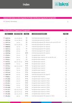
General information on Iskra Capacitors for Radio Interference Suppression Components ■ General information metallized polypropylene film capacitor 11 metallized polypropylene film capacitor 26 metallized polypropylene film capacitor with resistor (RC unit) 25 impregnated paper capacitor 36 impregnated paper capacitor with resisitor (RC unit) 37 impregnated paper capacitor 38 impregnated paper capacitor 39 impregnated paper capacitor 40 impregnated paper capacitor 41 impregnated paper capacitor 43 impregnated paper capacitor 44 impregnated paper capacitor...
Open the catalog to page 3
General Information Origin and spreading of interference There are two main sources of radio interference: devices, which due to their construction produce RF energy. These include generators for use in industry, medicine and science, as well as oscillators, radio and TV receivers etc. devices, which produce a wide spectrum of frequencies due to rapid variations in electrical current intensity. These include devices with switching components, thyristors, triacs, commutators and similar. Interference from source to receiver is spread in three ways: along conductors, by coupling and by radiation....
Open the catalog to page 4
General Information Maximum permitted interference limits In order to guarantee good operation of communicational and other equipment, radio interference must be tolerably limited. lnterference produced from the source are measured as follows: up to frequency 30 Mhz, interference voltages are measured which spread along the terminal in the supply network, above 30 MHz, strength of radiated field or radiated power on the terminal in the supply network is measured. Permitted levels of interference are given in the national and international regulations. Recommendations given by CISPR (Comite International...
Open the catalog to page 5
General InformationDefinitions taken from standards Class X capacitors Class X capacitors are suitable for applications where there is no danger of electrical shock in case of breakdown. Class X capacitors are divided into three subclasses (see table 1) according to the peak voltages of the pulses to which they are exposed during operation in addition to the line voltage. Such impulses can be caused by lightning in overhead lines, switching operations in neighbouring equipment or in the equipment which is shielded by the capacitor. Note: The increased electrical and mechanical safety is supposed...
Open the catalog to page 6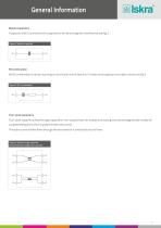
General Information Bipolar capacitors A capacitor with 2 connections for suppression of electromagnetic interference, see fig. 2. Figure 2: bipolar capacitor RC Combination An RC combination in series mounting is a functional unit of class X or Y, resistor and capacitor mounted in series, see fig. 3. Four-polar capacitors Four-polar capacitors (feed through capacitors/non-coaxial) have, for at least one coating, two electromagnetically mostly decoupled feeding lines which supply the electrical current. The active current either flows through the electrodes or is conducted around them. Figure...
Open the catalog to page 7
General Information Bypass capacitors Bypass capacitors branch off high frequency currents. There are three models in use: - single, - delta, - T-controls. The single capacitor consists of a capacitor in a metal housing to which a connection is fastened according to fig. 5a. The delta construction consists of one X-, and two Y2 capacitors which are connected in a triangle as in fig. 5b. The T construction consists of three capacitors C A, C B and C C - connected in T-shape as in fig. 5c. Figure 5a: single by-pass capacitor Figure 5c: example for a by-pass capacitor in T-wiring Rated voltage The...
Open the catalog to page 8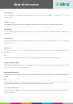
General Information Rated capacitance The rated capacitance of the capacitor is the capacitance value which characteries its rating for a temperature of 23 °C and after which it is named. Insulation resistance The insulation resistance is the ratio of the applied DC voltage to the current flowing after a stipulated time interval. Time constant The self-discharging time constant of the capacitor in seconds is the product of the insulation resistance in MΩ and the capacitance in µF. Dissipation factor The dissipation factor tan delta is the ratio of the effective output to the wattles power of...
Open the catalog to page 9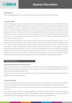
General Information Climatic category The climatic category defines the lower rated temperature/the upper rated temperature/the humidity class. Passive flammability The ability of the capacitor to burn with a flame as a consequence of the application of an external source of heat. The capacitor of filter suppresses RF by representing an inpendance for the higher frequencies which generally drop with frequency increase. By incorporating the capacitor in-parallel with the interference source, interferences are more or less short circuited. A capacitor incorporated in-parallel with power source...
Open the catalog to page 10
General InformationOrdering for interference suppression components When ordering, the following data should be given: - type of capacitor or filter - capacitance - voltage - inductance (for filters) - requirement for discharging resistor - terminal dimensions - current (for filters and four terminal capacitors) - special requirements for connecting components Length x height x width (mm) Pitch value Lead wire lenght (mm) Nominal voltage Capacitance tolerance Capacitance Type designation KPL3524 0.47 uF 2x0.022 uF + 2x1. mH + 470 kH 16 A 275 VAC Nominal voltage Current Discharging resistor Inductance Capacitance...
Open the catalog to page 11
Taping specification for radial capacitors(Robotic insertion) * Cumulative pitc error over any 20 pitches: max. ± 1 mm
Open the catalog to page 12
Electrical connection ■ Construction ■ Rated voltage ■ Capacitance tolerance ■ Climatic category ■ Passive flammability ■ Temperature range ■ Test voltage ■ Max. pulse rise time du/dt, at 390 V DC for 275 V AC and 425 V DC for 300 V AC ■ Insulation resistance at 20 °C , Um = 100 V DC, t = 1 min ■ Dielectric loss tan5 at f = 1 kHz and 20 °C ■ Soldering ■ Resistance to soldering heat ■ Self inductance ■ Complies to ■ Application polypropylene film, metallized 275 V AC, 300 V AC ± 20 % for C < 0.1 pF ± 10 % for C > 0.1 pF 40/100/56 acc. to IEC 60068-1 acc. to IEC 60384-14 -40 ° to +100 °C 2635 V...
Open the catalog to page 13All Iskra d.d. catalogs and technical brochures
 POWER ELECTRONIC CAPACITORS
51 Pages
 Strip Wound Cores
20 Pages
 Professional Batteries
4 Pages
 General Sales Conditions
4 Pages
 SparkWave SDR GE
2 Pages
 SparkWave High Speed PDH
2 Pages
 SparkWave SDR ADM
2 Pages
 SparkWave SDR STM
2 Pages
 SparkWave SDR GE2
2 Pages
 SparkLight ADM 16
2 Pages
 SparkLight ADM 1,4
2 Pages
 SparkLight HSP
2 Pages
 DZ9 Catalogue
2 Pages
 eMis
eMis27 Pages
 Bistable switch
26 Pages
 Low voltage switchgear
138 Pages
 ECU
ECU2 Pages
 NEO 3000
37 Pages
 FPC 200
4 Pages
 potentiometers
4 Pages
 Switch disconectors
7 Pages
 NFIF
NFIF4 Pages
 NFIB
NFIB4 Pages
 FI, NFI
2 Pages
 Bistable Switches
24 Pages
 DC-link and Snubber Capacitors
42 Pages
 Product line
20 Pages
 Power Factor Correction Banks
30 Pages
 Power Electronics Capacitors
5 Pages
 Dry Capacitors
4 Pages
 CAU380 Bay Computer
8 Pages
 MCE940 SCADA
4 Pages
 NEO3000 Substation System
8 Pages
 Energy Sector
52 Pages
 Energy meters
44 Pages
 Low voltage pfc
30 Pages
 DC link capacitors and snubbers
16 Pages
 Electrical measuring instruments
110 Pages


Archived catalogs
 POWER ELECTRONIC CAPACITORS
49 Pages
 Capacitors for electronics
44 Pages
 Lighting capacitors
28 Pages
 Capacitors Selection Guide
2 Pages
 Motor capacitors
28 Pages
 Capacitor banks - short form
4 Pages
 Moulded case circuit breakers
24 Pages
 Capacitor banks
32 Pages
 Induction heating capacitors
24 Pages
 DC link capacitors
2 Pages
 High-voltage power capacitors
24 Pages
 Overvoltage protection
72 Pages


- Bourn And Koch industrial PC
- Bourn And Koch data-logger
- Bourn And Koch switching relay
- Protection relay
- Bourn And Koch USB data-logger
- Bourn And Koch data-logger with screen
- Bourn And Koch automation PC
- Multimeter
- Bourn And Koch electromechanical relay
- Radio antenna
- DIN rail electric energy meter
- 12 V battery
- DC electromechanical relay
- Bourn And Koch contactor
- Portable multimeter
- Single-phase electric energy meter
- IEC battery
- Bourn And Koch programmable data-logger
- Industrial multimeter