
- Catalogs
- Iskra d.d.
- Low voltage pfc


Low voltage pfc

Low voltage pfc
Power factor correction equipment is crucial for enhancing electrical system efficiency by minimizing reactive power, which can incur additional costs and stress on transmission lines. The document describes various power factor correction banks, including individual, group, and central corrections, as well as automatic systems with harmonic filters.
Electrical devices often require reactive power, which can be compensated by installing capacitors. The document details the sources and effects of reactive power and offers methods for compensation, including formulas for calculating the necessary corrective power based on energy consumption and operating hours.
Three primary methods are discussed: individual correction for larger consumers, group correction for multiple consumers, and central correction from a central location. Detailed calculations for determining the required capacitor rating are provided using specific formulas and tables.
Examples illustrate the calculation of required corrective power and current discharge with power factor correction, demonstrating improvements in power factors and reductions in current loads on transformers and cables, facilitating the connection of new consumers.
Low voltage motors that are infrequently switched should be compensated with fixed capacitors. Guidelines for selecting the appropriate capacitor value based on motor type, speed, and load level are provided, along with considerations for quick motor discharge.
The document specifies the use of capacitors in motor and transformer systems to prevent overstrains and current shocks. Capacitors with 6 poles should be connected parallel to the motor winding if a switch is unavailable, with connection methods illustrated in figures.
The use of a motor's reactive power depends on motor type, speed, and load level. A formula for calculating the required capacitor power is provided, with a warning against quick discharging with larger capacitors due to self-excitation risks.
Transformers can be corrected using fixed capacitors. The document provides a formula for calculating transformer reactive power, noting that no-load reactive power is 1% to 3.5% of rated transformer power.
Tables provide power ratings of capacitors in relation to motor power, speed, load, and transformer voltage. The total correction power required in distribution transformers is advised to be 4% to 5% of rated power at an average load of 70%.
These banks are used for correcting low voltage transformers and can enhance the power of existing correction devices. They include safety features like overpressure disconnectors and discharge resistors.
Automatic banks are used for group and central correction of reactive power in distribution centers and industrial plants, available in outputs from 17.5 kvar to 300 kvar, and can be extended with additional cubicles.
The document outlines specifications for the KOK8411 type correction banks used for automatic correction of reactive power by filtering higher harmonics.
The device is a metal bank with a door for wall mounting, equipped with a ventilator for cooling.
Correction banks are intended for installation in production plants, distribution stations, and transformer stations, with specific site requirements.
The reactive power controller regulates reactive power by switching capacitor stages based on the network power factor.
The controller operates with a voltage supply of 400 V ± 10%, 50 Hz, and supports a range of settings for the desired cos ϕ.
An alarm system signals issues such as incorrect transformer connections and overcompensation, with alerts displayed on the front panel or remotely.
Catalog excerpts

Blindleistungskompensationanlagen Low Voltage Power Factor Correction Equipment
Open the catalog to page 1
Allgemeine Angaben: General information: Power Factor Correction Banks type KOK Reactive power Individuelle Kompensation Niederspannungsmotoren Individual power factor correction for low voltage motors Power factor correction for power transformers Fixed power factor correction banks Automatische Blindstromkompensationsanlagen Automatic power factor correction banks Automatische Blindstromkompensationsanlagen mit Filterung von hohen Harmonischen 20 Automatic power factor correction banks with harmonics filters Dauerkompensationsanlagen mit Filterung von hohen Harmonischen ^ Fixed power factor...
Open the catalog to page 3
Power Factor Correction Banks type KOK Reactive Power Quellen, Folgen und Zustandsverbesserung Sources, consequences and condition improvement Die meisten Elektrogeräte wie z.B. Asynchronmotoren, Drehstrom-Kollektormotoren, Umwandler, Drosselspulen, Induktionsöfen, Schweißgeräte, fluoreszierende Lampen u.v.a. benötigen für ihren Betrieb neben der Arbeitsenergie auch Blindstrom, was zusätzliche Kosten dafür nach sich zieht. Neben den Energieversorgungskosten belastet aber Blindstrom auch zusätzlich die Übertragungslinien und sonstige Elemente der Verbindungsstellen. Most electrical devices like...
Open the catalog to page 4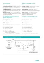
Methods of power factor correction Bekannt sind drei grundsätzliche Kompensationsarten: There are three basic methods of correction: Individuelle Kompensation - an größere Verbraucher wird unmittelbar die entsprechende Kondensatorenleistung angeschlossen. Individual correction - direct correction of a larger consumer by a suitable power capacitor Gruppenkompensation - an eine Verbrauchergruppe wird die entsprechende Kondensatorenleistung angeschlossen. Group correction - correction of a group of consumers by a suitable number of power capacitors Zentralkompensation - aus der zentralen Stelle...
Open the catalog to page 5
Beispiel 1 Stromverbrauch pro Monat (aus der Abrechnung) Monthly consumption of electrical energy required cos ϕ2 = 0,95 from Table 1 tg ϕ2 = 0,329 Der Typ und die Leistung der Anlage werden aus den Tabellen abgelesen. Bei Auswahl wird 20 - 30 % Reserve empfohlen, weshalb man in unserem Beispiel die Kompensationsanlage Typ KOK7116 300 kvar wählen soll. Type and power of device are chosen from the table. A reserve of 20 - 30 % is recommended when choosing the correction bank. Considering this, we need to choose KOK7116 300 kvar.
Open the catalog to page 6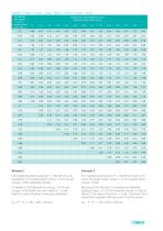
Tabelle 2: Faktor K1 (tg ϕ1 - tg ϕ2) /Table 2 : Factor K1 (tg ϕ1 - tg ϕ2) Vorhadener Leistungsfaktor cos ϕ1 Existing power factor cos ϕ1 Geforderter Leistungsfaktor cos ϕ2 Required power factor cos ϕ2 0,7 Die installierte aktive Leistung P = 100 kW mit Leistungsfaktor vor Kompensation cos ϕ1 = 0,74 soll auf cos ϕ2 = 0,95 verbessert werden. For installed active power P = 100 kW we want to improve the power factor cos ϕ1 = 0,74 to power factor cos ϕ2 = 0,95. In Tabelle 2, Schnittpunkt von cos ϕ1 = 0,74 und cos ϕ2 = 0,95 findet man den Faktor K1 = 0,58. Faktor K1 wird mit aktiver Leistung multipliziert:...
Open the catalog to page 7
Current discharge with PF correction Mit dem Einbau von Kompensationsanlagen werden Transformatoren, Kabel und sonstige Elemente der Energieausrüstung entlastet und damit Anschluss neuer Verbraucher ermöglicht. With power factor correction we reach current discharging of transformers, cables and other elements of energy plants. This allows the connection of new consumers. In Tabelle 3 findet man Faktor K2, mit dem man den Strom vor Kompensation multipliziert I1 bei cos ϕ1 auf cos ϕ2 nach Kompensation. Factor K2 from Table 3 must be multiplied with the current before correction I1 at cos ϕ1 to...
Open the catalog to page 8
Individuelle Kompensation Individual Correction Individuelle Kompensation wird in der Regel mit Dauerkondensatoren oder -anlagen ausgeführt. Somit werden Motoren und Transformatoren kompensiert. Individual power factor correction is normally achieved with fixed capacitors or devices. It is particularly suitable for individual power factor correction of motors and transformers. Individuelle Kompensation von Niederspannungsmotoren Individual Power Factor Correction for Low Voltage Motors Niederspannungsmotoren, die selten geschaltet werden, sollen aus technischen Gründen und wegen der Kosten mit...
Open the catalog to page 9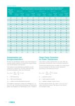
Tabelle 4/Table4 Motor-nennleistung Rated motor power (kW) Leistung der Kondensatoren in (kvar) in Hinsicht auf die Motorleistung, Drehzahl und Belastung Power rating of capacitor in (kvar) with respect to motor power, speed of rotation and load 3000 rev/min Vollbelastung full load Vollbelastung full load Vollbelastung full load Vollbelastung full load Vollbelastung full load Power Factor Correction for Power Transformers Ähnlich wie die Motoren werden auch die Energieumwandler häufig praktisch mit dauerhaft angeschlossenen Kondensatoren kompensiert. Like motors, power transformers can also often...
Open the catalog to page 10
Tabelle 5/Table 5 Nennleistung Umwandler Rated power of transformer (kVA) Leistungen der Kondensatoren in (kvar) in Hinsicht auf entsprechende Spannung und Belastung Power ratings of capacitor in (kvar) with respect to primary voltage and load 5 bis 10 kV Vollbelastung full load Vollbelastung full load Vollbelastung full load Die geforderte Kompensationsgesamtleistung in Distributionsumwandlern beträgt von 4 % bis 5 % der Nennleistung, d.i. bei durchschnittlicher Belastung von 70 %. The total correction power required in distribution transformers is 4 % to 5 % of rated power at an average load...
Open the catalog to page 11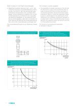
Dieser Anstieg ist in der Regel vernachlassigbar. This increase is usually negligible. • Moglichkeit paralleler Resonanz der 5. und 7. Har- monischen bei kleiner Umwandlerbelastung. Damit es dazu nicht kommt, darf die Leistung des ange- schlossenen Kondensators nicht die Werte uber- steigen, die auf Abbildung 5 angefuhrt sind, wo die Kondensatorleistung in Prozenten der Umwandler- nennleistung angegeben ist. Als praktische Orien- tierung wird angegeben, dass beim Umwandler mit einer Leistung bis 300 kVA die Kondensatorleistung bis zu 30 % der Umwandlerleistung betragen darf. Die Umwandleranschlussart...
Open the catalog to page 12All Iskra d.d. catalogs and technical brochures
 POWER ELECTRONIC CAPACITORS
51 Pages
 Strip Wound Cores
20 Pages
 Professional Batteries
4 Pages
 General Sales Conditions
4 Pages
 SparkWave SDR GE
2 Pages
 SparkWave High Speed PDH
2 Pages
 SparkWave SDR ADM
2 Pages
 SparkWave SDR STM
2 Pages
 SparkWave SDR GE2
2 Pages
 SparkLight ADM 16
2 Pages
 SparkLight ADM 1,4
2 Pages
 SparkLight HSP
2 Pages
 DZ9 Catalogue
2 Pages
 eMis
eMis27 Pages
 Bistable switch
26 Pages
 Low voltage switchgear
138 Pages
 ECU
ECU2 Pages
 NEO 3000
37 Pages
 FPC 200
4 Pages
 Radio Interfence
72 Pages
 potentiometers
4 Pages
 Switch disconectors
7 Pages
 NFIF
NFIF4 Pages
 NFIB
NFIB4 Pages
 FI, NFI
2 Pages
 Bistable Switches
24 Pages
 DC-link and Snubber Capacitors
42 Pages
 Product line
20 Pages
 Power Factor Correction Banks
30 Pages
 Power Electronics Capacitors
5 Pages
 Dry Capacitors
4 Pages
 CAU380 Bay Computer
8 Pages
 MCE940 SCADA
4 Pages
 NEO3000 Substation System
8 Pages
 Energy Sector
52 Pages
 Energy meters
44 Pages
 DC link capacitors and snubbers
16 Pages
 Electrical measuring instruments
110 Pages


Archived catalogs
 POWER ELECTRONIC CAPACITORS
49 Pages
 Capacitors for electronics
44 Pages
 Lighting capacitors
28 Pages
 Capacitors Selection Guide
2 Pages
 Motor capacitors
28 Pages
 Capacitor banks - short form
4 Pages
 Moulded case circuit breakers
24 Pages
 Capacitor banks
32 Pages
 Induction heating capacitors
24 Pages
 DC link capacitors
2 Pages
 High-voltage power capacitors
24 Pages
 Overvoltage protection
72 Pages


- Industrial computer
- Data logger
- Switching relay
- Protection relay
- USB datalogger
- Data-logger with screen
- Automation PC
- Electromechanical relay
- Multimeter
- Radio antenna
- 12 V battery
- DC electromechanical relay
- Contactor
- Portable multimeter
- IEC battery
- Programmable datalogger
- Industrial multimeter
- Current protection relay
- Digital protection relay