

- Company
- Products
- Catalogs
- News & Trends
- Exhibitions
TR-77D

TR-77D
- Upgradeable operating system and DPA framework.
- RF output power of 4 mW with a SAW filter for signal blocking.
- MCU with extended resources and low power modes.
- Includes SPI interface, serial EEPROM, and PWM output.
- Options for on-board or soldering antenna.
- Supply voltage: 3.0 V to 3.4 V.
- Operating temperature: -40 °C to +85 °C.
- Current consumption ranges from 56 nA to 21.5 mA across various power modes.
- RF sensitivity of -101 dBm with programmable output power in 7 levels.
- Hardware design affects RF range, including device construction and antenna orientation.
- Software can adjust RF output power and filter signals for noise immunity.
Catalog excerpts

RF Transceiver Module Series Data Sheet (((SGtfW Smarter Wireless. Simply. © 2018 IQRF Tech s.r.o. www.iqrf.org Datasheet TR-77D 180627 Page 1
Open the catalog to page 1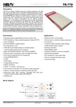
Description TR-77D is a family of IQRF transceiver modules operating in the 868 MHz license free ISM (Industry, Scientific and Medical) frequency band. Its highly integrated ready-to-use design containing MCU, RF circuitry, serial EEPROM and optional on-board antenna requires no external components. SMT mounting and very small dimensions allow space saving. Ultra low power consumption fits for battery powered applications. To be applicable for fire sensors and similar applications, unwanted signals are blocked by the SAW filter, only a subset of RF channels is allowed and maximal RF power is...
Open the catalog to page 2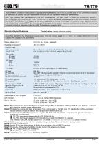
The information contained in this publication regarding device applications and the like is provided only for your convenience and may be superseded by updates. It is your responsibility to ensure that your application meets your specifications. IQRF Tech MAKES NO REPRESENTATIONS OR WARRANTIES OF ANY KIND TO STATED CONDITION, QUALITY, PERFORMANCE, MERCHANTABILITY OR FITNESS FOR PURPOSE and disclaims all liability arising from this information and its use. Use of IQRF Tech devices in life support and/or safety applications is entirely at the buyer’s risk, and the buyer agrees to defend, indemnify...
Open the catalog to page 3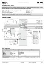
Absolute maximum ratings Stresses above listed maximum values may cause permanent damage to the device and affect device reliability. Functional operation under these or any other conditions beyond those specified is not supported. Voltage on Q4 to Q15 pins (configured as inputs) vs. GND -0.3 V to (Vcc + 0.3 V) Storage temperature -40 °C to +85 °C Ambient temperature under bias -40 °C to +85 °C Caution: Electrostatic sensitive device. Observe appropriate precautions for handling. For more information refer to datasheets of ICs used. © 2018 IQRF Tech s.r.o. www.iqrf.org Datasheet...
Open the catalog to page 4
General I/O pin UART TX PWM output General I/O pin UART RX SCK SPI clock input General I/O pin SPI data out SS/COUT General I/O pin Analog A/D input SPI Slave select Comparator output General I/O pin, programmable pull-up Interrupt / Wake-up on change (IOC) Green LED (LEDG) LED2 Red LED (LEDR) DACOUT D/A converter output IO / ADC RB4 General I/O pin, with programmable pull-up Interrupt / Wake-up on change (IOC) RFPGM / (X)LP mode termination AN11 Analog A/D input RE3 General input only pin IO / ADC / C-IN RA0 General I/O pin RC2 General I/O pin - Do not use, leave unconnected Note 8:...
Open the catalog to page 5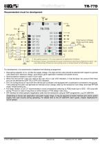
TR-77D Recommended circuit for development For development, it is recommend to implement the following arrangement: Decoupling capacitor on VCC to filter the supply voltage. The type and the value should be selected with respect to general rules observed in electronic design, according to given application hardware and power source. Serial protective resistors on each I/O pin used. When the Q10 and Q11 pins are used as the user I/Os or user LED indication, it must be taken into account that these pins can be affected by IQRF OS or DPA LED indication. Pin Q12 configured as an input with...
Open the catalog to page 6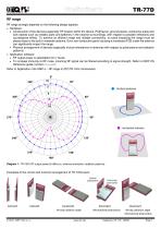
TR-77D RF range RF range strongly depends on the following design aspects: Hardware: Construction of the devices (especially TR location within the device, PCB layout, ground planes, conductive areas and bulk objects such as metallic parts and batteries in the nearest surroundings, with respect to possible reflections and counterpoise effect). To achieve an efficient range and reliable connectivity, no parts impacting the range must be placed close to the built-in meander antenna. Even non-conductive parts including a mainboard PCB under the antenna can significantly impact the range. Physical...
Open the catalog to page 7
Diagram 2A: Effective radiated power (ERP) vs. level in the setRFpower(level) function, TR-77DA, channel 57. Refer to IQRF OS Reference guide. Diagram 2B: Relative RF range vs. level in the setRFpower(level) function. TR-77D(A). Refer to IQRF OS Reference guide. Diagram 3: Relative effective radiated power (ERP) vs. channel, TR-77DA, with respect to channel 57 (100 %).
Open the catalog to page 8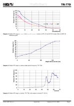
Relative range [%] Diagram 4: Relative RF range vs. level in the checkRF(level) function in STD, LP and XLP RX modes. Refer to IQRF OS Reference guide. 150 Height above terrain [cm] Diagram 5: Relative RF range vs. antenna height above the ground, TR-77DA. Diagram 6: Relative RF range vs. channel, TR-77DA, with respect to channel 57 (100 %).
Open the catalog to page 9
Diagram 7: Relative attenuation of received signal vs. channel, TR-77DA, with respect to channel 57 (100 %).
Open the catalog to page 10
© 2018 IQRF Tech s.r.o. www.iqrf.org Datasheet TR-77D 180627 Page 11
Open the catalog to page 11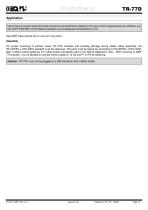
TR-77D Application Users have to ensure observing local provisions and restrictions relating to the use of short-range devices by software, e.g. the CEPT ERC/REC 70-03 Recommendation and subsequent amendments in EU. See IQRF video tutorial set on www.iqrf.org/videos. Assembly For proper mounting of surface mount TR-77Dx modules and avoiding damage during solder reflow assembly, the IPC/JEDEC J-STD-020C standard must be observed. The parts must be baked dry according to IPC/JEDEC J-STD-033C, MSL 4 before reflow soldering. For reflow profile and details refer to the AN010 Application note – SMT...
Open the catalog to page 12
© 2018 IQRF Tech s.r.o. www.iqrf.org Datasheet TR-77D 180627 Page 13
Open the catalog to page 13
TR-77D Sealing In case of sealing or protecting TR modules against a harsh environment by coating, encapsulating or potting using a lacquer, gel or other filling matter, the ion cleanness of the TR modules must be less than 1 µg/cm 2 of NaCl equivalent otherwise there is a risk of corrosion. Such a surface treatment always impacts the RF range. Thus, sealing material should have the relative permeability (µr) as close to 1 within given frequency band. E.g. µr = 4 at 868 MHz decreases relative range to approx. 70%. Protecting materials, methods, accomplishments and handling must comply with general...
Open the catalog to page 14All IQRF Tech catalogs and technical brochures
 IQD-REP-02-x1D IQRF Repeater
16 Pages
 DS-IOT-01 Quick Start Guide
20 Pages
 IQRF Quick Start Guide
18 Pages
 DS-START-04 Brief Manual
1 Page
 TR-76D
15 Pages
 TR-72D
13 Pages
 RF Range
15 Pages
 TR-78D
13 Pages
 TR-75D
14 Pages
 TR-72D series
12 Pages


- Communication gateway
- Industrial gateway
- Ethernet gateway
- Humidity and temperature probe
- Relative humidity and temperature sensor
- Wireless gateway
- IoT gateway
- Analog humidity and temperature sensor
- USB gateway
- Wall-mount humidity and temperature sensor
- Data transceiver
- Air humidity and temperature probe
- Radio transceiver module
- Humidity and temperature sensor for process applications
- Laboratory temperature sensor
- Flexible temperature sensor
- LAN gateway
- WiFi gateway