
- Catalogs
- ipf electronic gmbh
- CATALOG SENSOR TECHNOLOGY 3/3


- Company
- Products
- Catalogs
- News & Trends
- Exhibitions
CATALOG SENSOR TECHNOLOGY 3/3

CATALOG SENSOR TECHNOLOGY 3/3
- Conductive Probes: Available in different versions with varying probe lengths and materials. Operating temperature ranges from -15 to +150°C, pressure resistance from -1 to +20 bar, and degree of protection is IP65.
- Filling Level Relay (FV56): Used for monitoring conductive liquids with resistance up to 8MΩ. Features include adjustable turn-on delay, response sensitivity, and two potential-free relay outputs. Operating voltage is 20 to 253V AC/DC.
- Inductive Filling Level Sensors (FI52): Designed for bulk material monitoring on conveyors. Features include a pendulum length of 100 to 300mm, operating voltage of 10 to 30V DC, and degree of protection is IP67.
- Ensure the system is depressurized before installation.
- Avoid high temperatures and ensure sufficient space for mounting.
- Stabilize electrode rods longer than 0.5m with insulating spacers.
- For horizontal installations, maintain a slight downward orientation to prevent residue buildup.
- Use suitable cables with a maximum resistance of 25Ω per wire.
- Shielded cables are recommended in environments with strong electromagnetic interference.
- For process connections, use a wrench on the hexagon nut with a maximum torque of 100Nm.
- These devices should not be used in applications where personal safety depends on their functionality.
- Leakage and overfilling safeguarding.
- Dry-run protection for pumps.
- Two-step control in systems.
- Limit level monitoring in containers.
- Technology: Utilizes short electromagnetic pulses in the nanosecond range for measuring liquid levels in tanks. The sensors operate on a parallel rod design, ensuring high precision without the need for media comparison.
- Output: The time between sending and receiving pulses measures the distance traveled, outputting the current filling level via an analog output (4-20mA).
- Construction: Made from aluminum and stainless steel 1.4571, suitable for ambient temperatures from 0°C to +70°C.
- Installation Lengths: Available in 300mm, 500mm, and 800mm lengths with a G3/4" process connection and M12 electrical connector.
- Applications: Continuous filling level measurement, overfill protection, and dry-run protection.
- Technology: Designed for high operating comfort, these sensors feature a front-flush membrane and are capable of handling pressures up to 600bar.
- Output Options: Includes PNP, analog, and alarm outputs with programmable switching points and time delays.
- Construction: Stainless steel media-contacting parts, with a ceramic pressure transducer for low and negative pressure measurements.
- Features: Includes data logging, peak hold, self-monitoring functions, and a test function for simulating pressure values.
- Applications: Suitable for hydraulic aggregate pressure monitoring, vacuum checking, and compressor control.
- Electrical Data: Operating voltage of 12-32V DC, with short-circuit and reverse polarity protection.
- Mechanical Data: Pressure resistance up to 10bar, with a degree of protection rated at IP67 for filling level sensors and IP65 for pressure sensors.
- Connection: M12 connectors with 4-pin or 8-pin options, supporting various output configurations.
- Operating Range: Sensors are available with operating ranges from -1 to +600 bar, with connection options of 4-pin and 8-pin configurations.
- Technical Data: The sensors feature a peak value memory every 2ms, output signals including PNP, analog, and alarm outputs, and an operating voltage range of 12 to 32V DC. They have a maximum output current of 1A and a current consumption of less than 60mA without load.
- Accuracy and Output: Repeat accuracy is less than ±0.1% of the final value, with analog outputs of 0/4 to 20mA. The sensors include error recognition for line breaks and overloads.
- Protection and Material: The sensors are protected against short circuits and reverse polarity, with housing made of PA6.6 polyester and pressure transducers made of stainless steel or ceramic.
- Operating Principle: Flow sensors operate on the calorimetric principle, measuring the temperature difference between the medium and the sensor to determine flow conditions.
- Technical Data: They operate at 230V AC or 24V DC, with a power consumption of less than 8VA. The sensors have a response time of 1 to 13 seconds and a turn-off delay of 0 to 25 seconds.
- Applications: Suitable for dry-run protection for pumps, continuous monitoring of fluid flow, and temperature monitoring of different media.
- User Interface: The software provides a clear graphical layout for easy operation, with functions visible at a glance.
- Data Logging: Offers the ability to log measured values in an Excel table, with data logging triggered by time or measurement.
- Communication: The opto USB interface allows communication with the pressure sensor during operation.
- Includes mounting clips, cable sockets, and opto-adapters for USB interfaces.
- These devices should not be used in applications where the safety of a person depends on their functionality.
The temperature sensor operates between -20°C and +80°C, while the amplifier functions between -20°C and +60°C. The system can handle a temperature gradient of 250°C/min and supports a maximum line length of 100m between the sensor and amplifier. The sensor housing is made of V4A material, pressure-resistant up to 100 bar, and the amplifier is housed in plastic. The amplifier is mounted on a DIN-rail according to DIN EN 50022 standards.
Two potentiometers are used for calibration: the "Fein" for fine adjustment and the "Grob" for principal calibration. For stationary mediums, the sensor is installed and adjusted until the red LED lights up, with at least one green LED indicating flow. For flowing mediums, the sensor is adjusted until two green LEDs light up, with the red LED indicating a stationary medium. Adjustments for flow changes involve setting the potentiometer to light up specific LEDs, indicating flow status changes.
The LED indicators provide flow and temperature status: red indicates flow interruption or temperature exceedance, yellow indicates set flow achievement, and green indicates flow exceeding the set value. The relay status changes accordingly.
The flow sensors operate on the calorimetric principle, with a detection range for water between 1-150 cm/s and oil between 3-300 cm/s. They are pressure-resistant up to 100 bar and have an operating voltage of 24V DC ±20%. The sensors feature short-circuit and reverse polarity protection, with a degree of protection rated at IP67.
These sensors are used for continuous monitoring of fluid or gas flow, cooling systems, dry-run protection for pumps, and in various systems like ventilation, purification, and air-conditioning. They are suitable for use in corrosive or oxidative media with materials like Hastalloy or titanium available on request.
These devices should not be used in applications where the safety of a person depends on their functionality.
- Principle: Operate on the calorimetric principle, measuring flow by detecting temperature differences.
- Specifications: Operating range of 0.5 to 15 m/s, with a 24V DC operating voltage and a maximum output current of 200mA.
- Features: Include integrated amplifiers, potentiometers for setting switching points, and LED indicators for flow status.
- Applications: Used for monitoring air or gas flow, ensuring flow values in fan controllers, and preventing fan failures.
- Specifications: Measure temperatures from -40 to +300°C using PT100 resistance thermometers. They offer analog outputs and programmable switching functions.
- Features: Include a membrane keyboard for programming, an opto USB interface for communication, and self-monitoring functions for fault detection.
- Applications: Suitable for monitoring fluid and air temperatures in furnaces and machines.
- Flow Sensors: Ensure the sensor head is fully surrounded by the medium. Adjust settings using potentiometers and observe LED indicators for flow status.
- Temperature Sensors: Use the membrane keyboard or software for programming. The sensor can be rotated for optimal installation.
- These devices should not be used in applications where human safety depends on their functionality.
- For non-standard variants, contact IPF Electronic directly.
This document describes a compact temperature sensor designed for monitoring fluids and paste-like media in pipelines. The sensor features an adjustable switching point and a scalable 4-20mA analog output, with a measuring range from -40 to +120°C. It includes a window function for alternative monitoring, NC/NO contact settings, and a MIN/MAX memory. The device is programmable via a membrane keyboard and has a rotatable display for easy reading. It is protected against short circuits and reverse polarity, and connects via an M12 connector. The sensor is suitable for installation in T-pieces or welding sockets, with pressure resistance up to 100 bar.
- Operating voltage: 24V DC ±10%
- Output current: Max 200mA
- Voltage drop: Max 2.5V DC
- Time adjustment: 0-50s
- Pressure resistance: 100 bar
- Display: Yellow LED with 0.1°C resolution
- Protection: IP65
- Housing material: PBT, Sensor head: Stainless steel
The document also covers switching power supply units that convert unstabilized input voltage into a DC voltage. These units are more efficient and compact than conventional power supplies, with a high tolerance range for input voltage and frequency. They are mountable on a 35mm DIN-rail and feature overload and temperature protection.
- Output voltage: 24V DC ±1%
- Output current: Ranges from 2A to 20A
- Power consumption: Ranges from 48W to 480W
- Input voltage: 85-264V AC / 120-370V DC
- Frequency: 47-63Hz
- Protection: IP20
- Standards: UL 508, EN60950-1
- Temperature monitoring in pipelines
- DC voltage supplies from power grid
- Power supply units for diode lasers and arc welders
The document provides detailed specifications for various power supply units and multi-function counters. Key specifications include:
- Output voltage: 24V DC with an adjustment range of 24 to 28V DC.
- Output current: 40A with a nominal output power of 960W.
- Input voltage: 340 to 550V AC with a frequency of 47 to 63Hz.
- Temperature protection: Switch-off at temperatures below +100°C.
- Dimensions: 276x125.2x100mm with a weight of 0.8kg.
- Degree of protection: IP 20 according to EN 60529.
- Standards: UL 508, EN60950-1.
The power supplies are designed for 35mm DIN-rail mounting and feature connection terminals for both input and output. Specific terminal configurations are provided for different models, such as NCKB1001, NCLB2001, and NCLG4001.
The power supplies include:
- Overload protection ranging from 105 to 125% of output power.
- Temperature coefficient of ±0.03%/°C (0 to 50°C).
- Vibration resistance from 10 to 500Hz, 2g.
- Integrated protection devices for operational reliability.
- LED indicators for operational status: green for output voltage, yellow for input voltage, and red for overload.
The document also describes multi-function counters with features such as:
- Pulse, frequency, and elapsed-time counting capabilities.
- Programmable counting modes with options for fast and slow counting.
- LCD display with an 8-digit readout.
- Operating temperature range from -10 to +60°C.
- IP65 protection on the front side.
The document advises against using these devices in applications where human safety depends on their functionality. It also provides contact information for further inquiries and mentions the availability of accessories like cable sockets.
- Display: The counters feature LCD or LED displays with varying digit heights and capabilities such as simultaneous display of counter readings and preset values, scalable displays, and multi-colored options.
- Inputs and Outputs: The devices support potential-free relay outputs, programmable inputs (pnp/npn), and various counting methods including addition, subtraction, and phase discrimination.
- Data Storage: Data is stored via EEPROM with a retention period of over 10 years.
- Operating Conditions: The counters operate within specific voltage ranges (DC or AC) and have defined temperature and humidity tolerances.
- Protection and Durability: The devices are designed with IP65 protection for the front side, shock and vibration resistance, and are housed in durable materials like polycarbonate and Makrolon.
- Used in industrial processes such as mechanical engineering, plant construction, and production lines across various industries including metal, wood, plastic, paper, glass, and textiles.
- Specific applications include wear and maintenance counters, process visualization, timing relay functions, and frequency counting.
- CM03 Series: Features a two-line backlit LCD display, supports a maximum frequency of 60kHz, and includes functions like batch counting and grand total.
- 1200 Series: Offers LED displays with programmable counting methods, time delay relay functions, and a wide range of time counting options.
- 1400 Series: Includes pulse counters with programmable counting directions and selectable counting frequencies, suitable for part counting applications.
- Description: Designed for monitoring rotation speed in frequency-controlled drives, ensuring easy integration into both new and existing systems.
- Specifications: Utilizes current transformers (50A, 100A, 200A) to evaluate signals. Monitors frequency from 10 to 800Hz, with a maximum frequency set via a potentiometer. Activates an alarm relay if the frequency exceeds the set tolerance.
- Features: Compact dimensions (85 x 65 x 35.6mm), operates on +24V DC, and includes accessible screw terminals for easy installation.
- Applications: Motor speed control.
- Description: Suitable for various operational modes, including rotation speed, clock display, and linear measurement.
- Specifications: Operates on 17-30V DC or 115/230V AC, with a 6-digit LED display. Offers programmable outputs and interfaces (RS232/RS485).
- Features: Includes transducer power supply and adjustable scale factor.
- Applications: Speed measurement, piece counting, and stopwatch functions.
- Description: Electromagnetic components with high contact current rating, used for electrical isolation and switching high power levels.
- Specifications: Available with 1 or 2 change-over contacts, operating voltage options of 24V DC or 230V AC, and switching current up to 16A.
- Features: Includes LED display and robust screw terminals, suitable for DIN rail mounting.
- Applications: Electrical isolation and galvanic separation.
- Description: Used in connection technology for sensors and actuators, providing protection against moisture and dirt.
- Specifications: Available in various lengths and configurations, with options for LED displays and shielded jackets.
- Features: High mechanical resilience, vibration resistance, and resistance to coolants and lubricants.
- Applications: Connection between sensors and control units.
- Material: Outer sheath made of PUR, ensuring durability and resistance to environmental factors.
- Temperature Range: Operating temperatures range from -30°C to +90°C, depending on the model.
- Protection Degree: All products have an IP67 protection rating when properly screwed, indicating high resistance to dust and water.
- Voltage and Current: Various models support different voltage levels (up to 250V DC/ACeff) and nominal currents (up to 4A).
- Sockets: Available in M8 and M12 configurations, with options for angular or straight designs.
- Pin Configurations: Models are available with 3-pin, 4-pin, 5-pin, 8-pin, and 12-pin configurations.
- Lengths: Cables are available in lengths ranging from 0.3m to 20m, with some models featuring LED displays for operation and signal indication.
- Wire Assembly: Typically consists of 42 x 0.1mm or 43 x 0.1mm wire assemblies, with varying wire diameters depending on the pin configuration.
- Line Diameter: Ranges from 4.3mm to 6.3mm, depending on the model and pin configuration.
- Operating Voltage: Models support operating voltages from 10V to 250V DC/ACeff, with specific models featuring LED indicators for operation and signal.
- Ensure proper installation to maintain IP67 protection.
- Do not use these products in applications where human safety depends on their functionality.
- Consider environmental factors such as temperature and exposure to coolants and lubricants when selecting products.
- Operating Voltage: Ranges from 10V to 240V DC/ACeff depending on the model.
- Current: Typically 4A for most connectors.
- Wire Cross Section: Varies from 0.14mm2 to 0.75mm2.
- Operating Temperature: Generally between -25°C to +90°C.
- Protection Class: All connectors meet IP67 standards as per EN 60529.
- Materials: Outer jackets are made of PUR, with housing materials including PBT and nickel-plated brass. Contacts are typically CuZn, gold-plated.
- Types: M8 and M12 connectors available in straight and angular versions.
- Pin Configuration: Options include 3-pin, 4-pin, and 5-pin configurations.
- Connection Methods: Soldered connections and screw terminals are available.
- LED Displays: Some models include green and yellow LEDs for operation and signal display.
- Various lengths of connection cables are available, ranging from 0.3m to 5.0m.
- Additional accessories include highly flexible and shielded cables.
- Field attachment of plug connectors with fixed-cable devices or connection lines.
- Pre-fabrication of connectors with fixed-cable devices or connection leads.
- These devices should not be used in applications where the safety of a person depends on their functionality.
- Cable Sockets and Connectors: Available in M8 and M12 versions, both straight and angular. Rated voltage is 32V DC or 50V DC, with a rated current of 4A or 6A. Wire diameter ranges from 0.14 to 0.75mm², with PVC insulation. Operating temperature is -25 to +85°C, and protection is rated at IP67.
- Distributors: Designed for sensor and actuator connections, available in plastic and metal versions. Operating voltage is 10-30V DC, with a maximum output current of 2A per I/O signal. Features include LED status displays and a potential divider for circuit separation.
- Logic Modules: Used for linking sensor signals with AND/OR logic operations. Operating voltage is 10-30V DC, with a current consumption of 1A. Modules are available in various configurations, supporting up to 10 sensors.
- Ensure the cable sheath is pulled back to expose individual wires by about 30mm.
- Follow the sequence of pushing the coupling ring, cable support sleeve, and fitting sleeve over the cable, ensuring correct color coding.
- Secure the connector by screwing the coupling ring onto the fitting sleeve.
- Local collective distributor for vibration-proof sensor and actuator connections.
- Recommissioning of pre-tested machine parts with easy connection post-reconstruction.
- Signal linkage of multiple sensors using logic modules.
The document describes the use of ipf universal holders which eliminate the need for elaborate sensor holders. These holders allow for quick and secure sensor mounting in any position using a base module with a ball joint. The base module AY000088 is included in every fastening-parts kit, which contains necessary mounting materials. Application examples include sensor mounting on panels, rods, or profiles, and sensor adjustment and alignment.
Mechanical Tappets for Inductive Sensors
Mechanical tappets are used for precise switch-point definition with inductive proximity switches. They can withstand high mechanical stress and allow sensor exchange without dismantling the tappet. The document lists various holder and stop versions, materials, and dimensions.
Reflectors and Reflective Films
Reflectors made of weatherproof, UV-stabilized plastic are described. They use a prismatic reflector concept to reflect light back to the source. Various sizes and mounting options are available, with applications in reflex barriers and gate entrance monitoring.
Magnetic Linear Measurement Systems
The document details sensors for detecting linear or angular changes, using a magnetic tape and sensing head. The system provides high precision and is suitable for tough environments. Specifications include operating voltage, output current, and accuracy. Application examples include linear measurement under challenging conditions.
- The system consists of a sensing head and a magnetic tape, protected by a carrier strip and a stainless steel masking tape.
- Key features include a robust metal housing, easy installation, high initial acceleration, wear resistance, and high accuracy with a linear resolution of 10μm.
- The maximum measured length is 5120mm, and the system is insensitive to dirt, humidity, and vibration.
- Technical specifications include a sensing range of max. 1mm, output signal via RS485/SSI, operating voltage of 10-30V DC, and a repeat accuracy of max. 0.01mm.
- Used for detecting angles of rotation and rotary speeds, these encoders operate using photoelectric scanning.
- They emit two output signals in 90º phase quadrature, allowing the determination of rotation direction.
- Technical specifications include a maximum rotation speed of 10,000 min-¹, output frequency of max. 150kHz, and a voltage supply of 4.75-30V DC.
- Includes measuring wheels, angle brackets, clamping claws, couplings, and cable sockets.
- Measuring wheels are available with different circumferences and materials to suit various applications.
- Factors affecting measuring accuracy include material type, torque, transportation speed, and surface roughness.
- Devices should not be used in applications where safety depends on their functionality.
- Ensure correct alignment of system components during installation.
Radar motion sensors are discussed, focusing on their applications and specifications.
This section covers various types of optical sensors including through-beam sensors, retro-reflective sensors, and diffuse reflection sensors. High-performance through-beam sensors with amplifiers are also highlighted.
Details on fiber optic amplifiers, glass fiber optics, and plastic fiber optics are provided, emphasizing their uses and advantages.
Different types of light barriers such as fork, angular, frame, and ring light barriers are described.
This section includes through-beam sensors, retro-reflective light barriers, diffuse reflection sensors, and measuring systems.
IPF Opti-Check camera sensors and their accessories are discussed.
Includes color sensors, luminescence diffuse reflection sensors, and contrast scanners.
IPF SAFE safety light curtains, safety relays, and accessories are covered.
Capacitive, inductive, and conductive filling level sensors, along with conductive filling level relays and accessories, are detailed.
Pressure, flow, and temperature sensors are discussed in this section.
Information on switching power supply units and power output stages is provided.
Includes multi-function counters, pulse counters, elapsed-time counters, time-delay relays, measuring transducers, monitors, and coupler relays.
Various accessories such as cable sockets, distributors, logic modules, signal inverters, sensor testers, fixing materials, mechanic tappets, and reflectors are listed.
Magnetic linear measurement systems, encoders, and their accessories are discussed.
Catalog excerpts

EN Subject to alteration! Version: 07.03.2018
Open the catalog to page 1
IPF ELECTRONIC ipf electronic gmbh Kalver Strafe 25 - 27 58515 Ludenscheid Germany Tel +49 2351 9365-0 Fax +49 2351 9365-19 [email protected] www.ipf-electronic.com I Capacitive filling level sensors I Inductive filling level sensors I Conductive probes I Conductive filling level relays I Accessories Filling level sensors I Pressure sensors I Flow sensors I Temperature sensors Fluid technology I Switching power supply units I Power output stages I Multi-function counters I Pulse counters I Elapsed-time counters I Time delay relays I Measuring transducers I Monitors I Coupling relays I Cable...
Open the catalog to page 2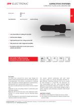
level detection M30 x 1,5 G%" Gl" operating point media touching P very insensitive to soiling of any kind P LED function display P high-quality parts for a long service life P fully electronic with integrated amplifier P DC-devices with short-circuit and reverse polarity protection description All media that surround the sensor head change the dielectric balanced state between the meter electrode and the surrounding space. This process is converted to a switching signal. The optimum sensitivity adjustment is performed by a potentiometer that is covered with a plastic screw. The sensor should...
Open the catalog to page 4
article-no. version output article-no. version output TECHNICAL DATA operating point media touching the sensor tip output signal see above current consumption (w/o load) < 4mA output current (max. load) 400mA voltage drop (max. load) 1V DC switching current (min. load) - display (signal) yellow LED display (operation) - sensitivity adjustment potentiometer reverse polarity protection + media touching the sensor tip see above 20 . 250V AC ■< 2.5mA 400mA 8V AC 5mA 10Hz yellow LED potentiometer housing material PTFE (teflon) ipf electronic gmbh • Kalver StraGe 25 - 27 • 58515 Ludenscheid • Germany...
Open the catalog to page 5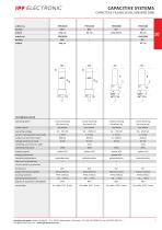
reverse polarity protection + - + housing material PTFE (Teflon) PTFE (Teflon) PTFE (Teflon) PTFE (Teflon) connection 2m cable, PVC, 3-wire 2m cable, PVC, 2-wire 2m cable, PUR, 4-wire 2m cable, PUR, 2-wire ipf electronic gmbh • Kalver StraGe 25 - 27 • 58515 Ludenscheid • Germany | Tel +49 2351 9365-0 • Fax +49 2351 9365-19 | [email protected] • www.ipf-electronic.com
Open the catalog to page 6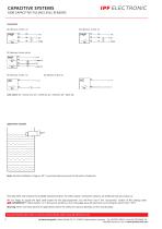
CAPACITIVE SYSTEMS 1000 CAPACITIVE FILLING LEVEL SENSORS connection DC-devices, 3-wire, no wire colors: bn = brown (1), wh = white (2), bu = blue (3), bk = black (4) application example Note: Slanted installation of approx. 20° is recommended to prevent the formation of deposits. This data sheet only contains the available standard variants. For other output / connection variants, we kindly ask that you contact us. We are happy to supply the right cable socket for the plug equipment. You will find a list in the “accessories” section of the catalog under -SENSORFLEX® “cable sockets” or in the...
Open the catalog to page 7
0 46 x 95mm 0 60 x 95mm connection pipe thread G% P simple filling level detection by screwing in capacitive sensors P Teflon sleeve: anti-electrostatic, resistant to acids and bases P Crastin sleeve, pressure-proof to 6 bar P sensor installation after mounting of the sleeve P alignment of the sensors under operating conditions mounting sleeves for reliable filling level measurements description The mounting sleeves are used to hold capacitive sensors. All media that surround the mounting sleeve also influence the installed sensor. The dielectric balanced state between the meter electrode of...
Open the catalog to page 8
TECHNICAL DATA housing material PTFE (teflon) ipf electronic gmbh • Kalver StraBe 25 - 27 • 58515 Ludenscheid • Germany | Tel +49 2351 9365-0 • Fax +49 2351 9365-19 | [email protected] • www.ipf-electronic.com
Open the catalog to page 9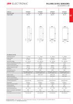
ipf electronic gmbh • Kalver StraGe 25 - 27 • 58515 Ludenscheid • Germany | Tel +49 2351 9365-0 • Fax +49 2351 9365-19 | [email protected] • www.ipf-electronic.com
Open the catalog to page 10
FILLING LEVEL SENSORS connection cable device DC wire colors: bn = brown (1), bu = blue (3), bk = black (4) Note: To achieve full pressure resistance, the thread should engage approximately 20mm. It may be necessary to attach a threaded flange to the container wall. The thread is sealed either with hemp and a sealing paste acc. to DIN-DVGW or, for greater chemical resistance, with Teflon sealing tape. When screwing in, the specified thread torque must not be exceeded. This data sheet only contains the available standard variants. For other output / connection variants, we kindly ask that you...
Open the catalog to page 11
level detection probe length 500mm1000mm 1600mm P process pressures up to 20bar P process temperature up to +150°C description The electrode probes from ipf electronic are used in combination with the corresponding filling level relays for conductive limit level detection in electrically conductive filling materials. The electrode rods are fastened to a process connection, whereby the rods may have a length of up to 1600mm. To differentiate between different filling levels, the electrode rods can be shortened to the desired length. With up to five contact electrodes, multiple tasks can be fulfilled...
Open the catalog to page 12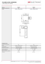
connection sensing element GJ4" GJ4" TECHNICAL DATA connection sensing element G!4" housing material POM-polyoxymethylene sensing element material stainless steel 1.4404 insulation: PA-polyamide ipf electronic gmbh • Kalver StraGe 25 - 27 • 58515 Ludenscheid • Germany | Tel +49 2351 9365-0 • Fax +49 2351 9365-19 | [email protected] • www.ipf-electronic.com
Open the catalog to page 13
connection housing 0 40mm TECHNICAL DATA connection sensing element version housing material sensing element material operating temperature operating pressure resistance degree of protection (EN60529) connection ipf electronic gmbh • Kalver StraGe 25 - 27 • 58515 Ludenscheid • Germany | Tel +49 2351 9365-0 • Fax +49 2351 9365-19 | [email protected] • www.ipf-electronic.com
Open the catalog to page 14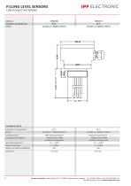
connection sensing element G1J4" G1J4" TECHNICAL DATA connection sensing element G1!4" housing material POM-polyoxymethylene sensing element material stainless steel 1.4404 insulation: PA-polyamide ipf electronic gmbh • Kalver StraGe 25 - 27 • 58515 Ludenscheid • Germany | Tel +49 2351 9365-0 • Fax +49 2351 9365-19 | [email protected] • www.ipf-electronic.com
Open the catalog to page 15All Ipf electronic gmbh catalogs and technical brochures


Archived catalogs
 CATALOG SENSOR TECHNOLOGY 1/3
394 Pages
 ROTARY ENCODER PROGRAMMABLE
2 Pages
 SAFETY LIGHT CURTAINS
12 Pages
 HIGHSPEED CAMERA SYSTEMS
12 Pages
 CATALOG LED LIGHTS
80 Pages
 INDUCTIVE SENSORS
24 Pages
 LED HAND LAMP
2 Pages
 CATALOG SENSOR TECHNOLOGY 2/3
286 Pages
