
- Catalogs
- ipf electronic gmbh
- CATALOG SENSOR TECHNOLOGY 2/3


- Company
- Products
- Catalogs
- News & Trends
- Exhibitions
CATALOG SENSOR TECHNOLOGY 2/3

CATALOG SENSOR TECHNOLOGY 2/3
1. Normally Closed Contact Function (NC): The switching output is wired via PIN2, requiring a 4-wire cable socket and connection via the white wire.
2. Alternating Current Devices: Typically 2-wire without short-circuit protection, requiring a minimum load current of 2mA.
3. Proximity Switches with Analog Output: Used in control and measurement, producing linear voltage (0-10V) or current (4-20mA).
1. Series Connection: Maximum of 3 devices can be connected in series, considering voltage drop.
2. Parallel Connection: Requires decoupling diodes and a logical OR-gate for 3-wire PNP-sensors.
1. Flush Sensors: Active face may be level with backing material.
2. Non-Flush Sensors: Must protrude, using 2x the nominal switching distance.
3. Tightening Torques: Specific torques for different thread materials to avoid damage.
Defines maximum switching operations per second, influenced by sensor size and oscillation time.
1. Switching Distance (Sn): Varies from 0.6mm to 3.0mm depending on the model.
2. Operating Voltage: 10-30V DC.
3. Current Consumption: ≤ 5.5mA or ≤ 15mA without load.
4. Output Current: Maximum load of 100mA or 200mA.
5. Protection: Includes short-circuit and reverse polarity protection.
6. Operating Temperature: -25 to +70°C.
7. Degree of Protection: IP67.
1. Nominal Switching Distance: Distance at which a metal part changes the state of the switch.
2. Repeatability: Accuracy of measurements under standardized conditions.
3. Correction Factor: Adjusts switching distance based on material type.
Devices should not be used where safety depends on their functionality.
- Switching Distance (Sn): Ranges from 1.5mm to 4.0mm depending on the model.
- Operating Voltage: 10 to 30V DC across all models.
- Current Consumption: ≤ 15mA without load.
- Output Current (Max Load): 200mA for all models.
- Voltage Drop (Max Load): 2.0V DC.
- Norm Measuring Plate: Complies with EN 60947-5-2.
- Hysteresis: Less than 15%.
- Repeat Accuracy: As per EN 60947-5-2.
- Correction Factor: Varies by material (St37: 1; V2A: ~0.7; Ms: ~0.4; Al: ~0.3; Cu: ~0.2).
- Switching Frequency: 1kHz.
- Display Signal: Yellow LED.
- Protection Features: Short-circuit and reverse polarity protection included.
- Dimensions: Typically M8x1 with varying lengths.
- Housing Material: Stainless steel or nickel-plated brass.
- Operating Temperature: -25 to +70°C.
- Degree of Protection: IP67.
- Connection Types: Options include 2m PVC or PUR cables, M8 or M12 connectors.
Product Variants and Features:
- Multiple models with different switching distances and designs (standard, short, top-series).
- Output signals available in PNP or NPN, normally open (NO) or normally closed (NC).
- Mounting options include flush and non-flush designs.
- Connection accessories and mounting clips are available for various models.
Key Considerations:
- Ensure compatibility with EN 60947-5-2 standards for measuring plates.
- Consider correction factors based on material type for accurate application.
- Verify connection type and accessories for installation requirements.
Catalog excerpts

EN Subject to alteration! Version: 07.03.2018
Open the catalog to page 1
IPF ELECTRONIC ipf electronic gmbh Kalver Strafe 25 - 27 58515 Ludenscheid Germany Tel +49 2351 9365-0 Fax +49 2351 9365-19 [email protected] www.ipf-electronic.com I Norm switching distances I Increased switching distances I All-steel sensors I Analog sensors I High-temperature sensors I Ring sensors I Pressure-proof sensors I Welding-proof sensors Inductive sensors I Metal devices I Plastic devices Capacitive sensors I Magnetic proximity switches I Cylinder sensors I Magnetic high-temperature sensors I Accessories I Diffuse reflection sensors I Retro-reflective light barriers I Radar...
Open the catalog to page 2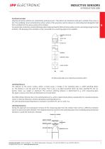
INDUCTIVE SENSORS functional principle Inductive proximity switches are contactlessly working sensors. They detect all conductive metal parts, whether they move or not. The oscillating circuit coil behind the active surface of the proximity switch produces an alternating electromagnetic field that is emitted from the active surface of the initiator. Any electrically conductive material (damping object) approaching the field will induce eddy currents, extracting energy from the oscillator. The damping of the oscillator is then converted into a switching signal in the amplifier. functional principle...
Open the catalog to page 4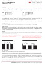
INDUCTIVE SENSORS output circuit For the switching outputs of DC devices, a differentiation is made between PNP and NPN. For PNP outputs the load is connected in such a way that it is energized (positive switching) when the sensor is driven to full output (damping). NPN devices maintain their load permanently energized, switching the earth connection only (negative switching). A corresponding wiring diagram is supplied with every sensor. The alternating current devices are usually 2-wire devices without short-circuit protection. Consequently a load must be connected, which allows for a minimum...
Open the catalog to page 5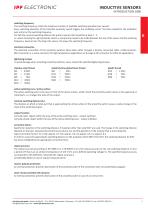
switching frequency The switching frequency states the maximum number of available switching operations per second. Every switching operation of the inductive proximity switch triggers the oscillating circuit. The time needed for the oscillation puts a limit on the switching frequency. For half the nominal switching distance the pulse to pause ratio should be at least 1 : 2, i.e. when choosing the right proximity switch, a compromise needs to be made between the size of the sensor and the switching frequency. General rule: The larger the sensor, the lower the switching frequency. electrical connection...
Open the catalog to page 6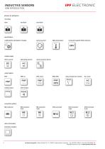
INDUCTIVE SENSORS 1000 INTRODUCTION glossary for pictograms mounting flush specifications unaffected by atmospheric changes high temperature increased magnetic field resistance voltage supply direct current alternating current universal power device analog output alarm output relay, change-over contact other information protective isolation ipf electronic gmbh • Kalver Straße 25 - 27 • 58515 Lüdenscheid • Germany │ Tel +49 2351 9365-0 • Fax +49 2351 9365-19 │ [email protected] • www.ipf-e
Open the catalog to page 7
standard, short, preferential, top U standard design U short design U preferential series U top-series ipf electronic gmbh • Kalver StraGe 25 - 27 • 58515 Ludenscheid • Germany | Tel +49 2351 9365-0 • Fax +49 2351 9365-19 | [email protected] • www.ipf-electronic.com
Open the catalog to page 8
INDUCTIVE SENSORS 1100 NORM SWITCHING DISTANCES ipf electronic gmbh • Kalver Straße 25 - 27 • 58515 Lüdenscheid • Germany │ Tel +49 2351 9365-0 • Fax +49 2351 9365-19 │ [email protected] • www.ipf-e
Open the catalog to page 9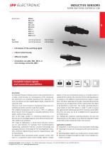
non-flush switching distance 2.0 to 15mm P LED display of the switching signal P robust metal housing P different lengths P connection via cable, M8-, M12- or microchange-connector (MC) description An important feature of these sensors is the cast electronics in a stable, metal housing. As a consequence of the compound, the electronics are perfectly protected from vibrations. As such, the devices are also sealed against fluids, except for the connector side. They are much more resistant to mechanical stress than conventional proximity switches made from plastic. The ambient temperature can be...
Open the catalog to page 10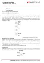
INDUCTIVE SENSORS 1100 NORM SWITCHING DISTANCES Notes on inductive proximity switches I inductive sensor flush, preferential series flush, standard and short design, top-series non-flush, preferential series non-flush, standard and short design, top-series functional principle The oscillation coil behind the active surface of the proximity switch produces an alternating electromagnetic field. Any electrically conductive material entering the field will induce rotational currents extracting energy from the oscillating circuit. The damping of the oscillator is then converted into a switching signal...
Open the catalog to page 11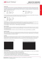
INDUCTIVE SENSORS NORM SWITCHING DISTANCES 1100 output circuit For the switching outputs of direct current devices a differentiation is made between PNP and NPN. For PNP outputs the load is connected in such a way that it is energized (positive switching) when the sensor is driven to full output (damping). NPN devices maintain their load permanently energized, switching the earth connection only (negative switching). A corresponding wiring diagram is supplied with every sensor. For devices with M12-connector and normally closed contact function (nc), the switching output is wired via PIN2. For...
Open the catalog to page 12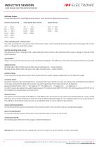
INDUCTIVE SENSORS 1100 NORM SWITCHING DISTANCES tightening torques To avoid damage when mounting proximity switches, never exceed the tightening torque given. stainless steel thread nickel-plated brass thread plastic thread active switching zone / active surface: The active switching zone is the area in front of the active surface, within which the proximity switch reacts to the approach of metal parts, i.e. changes the state of the output. nominal switching distance (Sn): The distance at which a metal part that is approaching the active surface of the proximity switch causes a change in the...
Open the catalog to page 13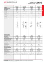
ipf electronic gmbh • Kalver StraGe 25 - 27 • 58515 Ludenscheid • Germany | Tel +49 2351 9365-0 • Fax +49 2351 9365-19 | [email protected] • www.ipf-electronic.com
Open the catalog to page 14All Ipf electronic gmbh catalogs and technical brochures


Archived catalogs
 CATALOG SENSOR TECHNOLOGY 1/3
394 Pages
 ROTARY ENCODER PROGRAMMABLE
2 Pages
 SAFETY LIGHT CURTAINS
12 Pages
 HIGHSPEED CAMERA SYSTEMS
12 Pages
 CATALOG LED LIGHTS
80 Pages
 INDUCTIVE SENSORS
24 Pages
 LED HAND LAMP
2 Pages
 CATALOG SENSOR TECHNOLOGY 3/3
222 Pages

- Power supply unit
- Flowmeter
- DC power supply
- Electrical cable
- Digital imager
- AC/DC power supply
- Volume flow monitor
- Liquid flow monitor
- Angular encoder
- Copper cable
- Industrial camera module
- Copper electrical cable
- Pressure transmitter
- Infrared imager
- Proximity switch
- Incremental encoder
- Analog pressure transmitter
- Push-button switch
- Level probe