Catalog excerpts

GEARBOX MOTOR 2,0 rpm with 230V - AC synchronous motor Rated voltage Rated frequency Rated current Rated power Rated speed Rated torque Max torque Stall torque Note: 1) 2) 3) 4) Starting voltage Operating temperature Operating humidity Rotation Sound pressure level IP rate Type of service 170 V from -10°C to +70°C 10 – 90 % R.H. (no condensation) CW / CCW 45/46 dB(A) at 1 m IP 20 S3 (10%-80% duty cycle) Gearbox motor can operate with a torque load on the slow shaft from 0 Nm to max torque value. The stall torque is the condition over which the gearbox motor is not able to operate. If the gearbox motor operates over the max torque, its life is reduced drastically. To avoid reverse rotation, turn on the gearbox motor observing the zero crossing. Electrical and mechanical characteristics Insulation Class Class F Appliance Class Class 0I Capacitor value 0,56 μF / 450V① Dielectric strength test 1800V 50Hz for 1 s Insulation resistance 100 MΩ min Reduction rate 246,7:1 Axial play slow shaft 0,5 mm max Backlash (no load) 2,0° max Mounting position Any Note: Item Gearbox shells Plastic gear Metal gear Pinion Shaft ring Sleeve bearing Motor bearing Grease Material / References Aluminium alloy PA66 Sintered SB4050 and steel steel PA66 Sintered bronze Ball bearing NMB – 626ZZ EUBO® C373 TDS ① the capacitor is in compliance with IEC EN 60252-1 standard Radial and axial load Radial and axial load applied to the slow shaft reduce the life of gearbox. We suggest do not exceed 250N of radial load and 200N of axial load. This revision replaces all previous versions of this document. IPC has done every effort to ensure that all information in this document is complete and correct at the time of publication. Due to possible product improvements, we reserve the right to change certain data in this document without prior notice. Rev. 1
Open the catalog to page 1
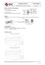
GEARBOX MOTOR 2,0 rpm with 230V - AC synchronous motor Electrical connection and wiring diagram Electrical connections: No 3 male terminals 6,3 x 0,8mm Direction of rotation: CW or CCW rotation looking at exit of the slow shaft. Marking Example of label. For the correct data of this model, please referred to the ones written on the first page of this specification Standard applied Low Voltage Directive: EN 60335-1 EMC Directive: Emission – EN 55014-1, EN 61000-3-2 and 61000-3-3 Immunity – EN 55014-2 Performance curves This revision replaces all previous versions of this document. IPC has...
Open the catalog to page 2All IPC catalogs and technical brochures
-
CENTRIFUGAL FAN CFH21203H501
2 Pages
-
CENTRIFUGAL FAN CFH21203H401
2 Pages
-
EXHAUST BLOWER AVFLVIS001
3 Pages
-
EXHAUST BLOWER AVH2A1203H301
2 Pages
-
EXHAUST BLOWER BLXMS00031
2 Pages
-
EXHAUST BLOWER BLH2A150202
2 Pages
-
CROSS FLOW FAN CRW2A624BRC2
1 Pages
-
GEARBOX MOTOR GMF215D901
2 Pages
-
CENTRIFUGAL FAN CFX2131901
2 Pages
-
CENTRIFUGAL FAN CFX2130702
2 Pages
-
CENTRIFUGAL FAN CFH2080804
2 Pages
-
CENTRIFUGAL FAN CBX4190411
2 Pages
-
Micro Motion Systems
64 Pages
-
EXHAUST BLOWER AVFLVALD22
3 Pages
-
EXHAUST BLOWER BLXM000003
2 Pages
-
EXHAUST BLOWER BLH2A150201
2 Pages
-
AUTOMATION PRODUCTS
10 Pages
-
HVAC-R PRODUCTS
8 Pages


