
- Catalogs
- Invertek Drives Ltd.
- Fieldbus User Guide


- Products
- Catalogs
- News & Trends
- Exhibitions
Fieldbus User Guide
1 /62Pages
Fieldbus User Guide
1 /62Pages
Catalog excerpts

InvertekDrives.com User Guide FIELDBUS User Guide About This Document Fieldbus Connectivity Parameter Configuration for Fieldbus Operation Ethernet Connection Internal Webserver
Open the catalog to page 1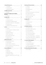
11.4. Addilional Modbus RTU Registers / CAN Index 4.4. Modbus RTU Status & Control Holding Registers.. 10 5.2. CAN Communication Configuration Parameter... 11 6.4. Optional Interface for Compact 2 Basic Drives ... 17 75. Creating an Additional User Accounl for Limited ^ 8.5. Process Data Exchange (cyclic communication)... 23 10.7. Profibus DP Gateway Features - OD-PROFB-IN . 51 10.8. DeviceNet Gateway Features - OD-DEVNT-IN. 52 2 | Fieldbus Guide | Version 1.02
Open the catalog to page 2
All rights reserved. No part of this User Guide may be reproduced or transmitted in any form or by any means, electrical or mechanical including photocopying, recording or by any information storage or retrieval system without permission in writing from the publisher. This document is the "original instructions" document. All non-English versions are translations of the "original instructions". The contents of this document are believed to be correct at the time of printing. In the interest of a commitment to a policy of continuous improvement, the manufacturer reserves the right to change the...
Open the catalog to page 3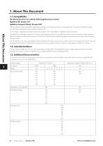
About This Document 1. About This Document1.1. Compatibility This Document is for use with the following firmware versions: Optidrive Compact 2 Basic: Version 2.07 This document provides information regarding parameters and programming for all Invertek Drives' Optidrive E3 product families including the Optidrive E3 based Compact 2 Basic units. For information regarding installation and technical data, refer to the relevant Installation Guide document. Invertek Drives Ltd adopts a policy of continuous improvement and whilst every effort has been made to provide accurate and up to date information,...
Open the catalog to page 4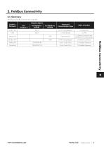
The following fieldbus networb are supported: Fieldbus Connectivity www.mvertekdrives.com Version 1.02 Fieldbus Guide
Open the catalog to page 5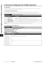
Parameter Configuration for Fieldbus Operation 3. Parameter Configuration for Fieldbus Operation3.1. Overview The following parameters are used to configure any fieldbus connection. Refer to the Programming Guide for further information. Parameters are explained more fully in the Programming Guide. 3.1.1. Parameter P-12: Control Source The fieldbus interfaces may be used to monitor information from the drive regardless of where the control commands originate. If it is required to control the drive through the fieldbus interface, the following parameter should be adjusted as shown. Function: Control...
Open the catalog to page 6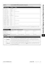
Reference: P-63 Function: Modbus RTU Mode Selection E3 IP20, IP66NS E3 IP66S Minimum: Parameter Configuration for Fieldbus Operation Fieldbus Information: CAN Index: 20A3h Modbus Register: 191 Format: UINT Units: N/A Description: Setting www.invertekdrives.com Version 1.02 | Fieldbus Guide | 7
Open the catalog to page 7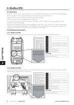
Modbus RTU communication is supported using Function Codes 03 Read Holding Registers and 06 Write Single Holding Register. All internal registers are Holding registers. TFiere are no other register types present within the drive. Registers 1 to 4 only support Function Code 16 Write multiple Holding Registers. Modbus RTU communication is enabled by default for Read access. To control the drive through Modbus RTU, parameter P-12 should be set to 3 or 4. Refer to the programming guide for further information on the parameter settings. When an external Modbus RTU device is used to control the drive,...
Open the catalog to page 8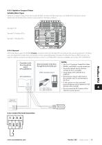
4.2.3. Optidrive Compact 2 Basie Suitable Motor Types Optidrive Compact 2 Basic drives also include the RJ45 connector with the same layout as Optidrive E3 units shown above. Additionally, the Modbus RTU interface is also present on terminals as follows: All Invertek drive's support the RS485 3-wire connection method for Modbus RTU according to the network specification. The three wires are essential to transfer data and maintain common potential between all nodes. For drives that have an RJ45 connector an optional interface connector providing terminals to connect to a Modbus RTU network is...
Open the catalog to page 9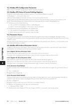
4.3. Modbus RTU Configuration Parameter Refer to section 3. Parameter Configuration for Fieldbus Operation on page 6. 4.4. Modbus RTU Status & Control Holding Registers Modbus RTU status holding registers are shown in section 11. Control & Status Registers on page 54. Holding Register 1 - 4 are used for drive control. Additional Holding registers provide status information which may be read from the drive. Modbus Master devices differ between different manufacturers and so it may be necessary to review the documentation for the specific Master device being used to understand the correct addressing...
Open the catalog to page 10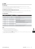
The CAN communication profile is implemented according to the specification DS301 version 4.02 of CAN in automation (www.can-cia.de). Specific device profiles such as DS402 are not supported. CAN communication is enabled by default however to use any control functions parameter P-12 must be set to 7 or 8. Refer to the Programming Guide for further Information. 5.2. CAN Communication Configuration Parameter The CAN communication baud rate can be set by using parameter P-36. Available baud rates are: 125kbps, 250kbps, 500kbps, 1 Mbps, (with default settings as 500kbps). The Node ID is set up through...
Open the catalog to page 11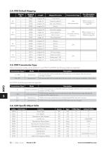
12 | Fieldbus Guide | Version 1.02
Open the catalog to page 12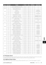
All user adjustable parameters are accessible through the CAN communication interface. The Programming Guide document provides the Index for each parameter along with any scaling or information how the data for each parameter is stored. Further additional status Indices are present in the drive. These are described in section If. Control & Status Registers on page 54. Version 1.02 | Fieldbus Guide | 13
Open the catalog to page 13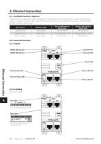
6. Ethernet Connection 6.1. Available Interface Options Ethernet interfaces are optionally available for Optidrive E3 and Optidrive Compact 2 products which support either Ethernet/IP protocol or Modbus TCP protocol. Part numbers for these interfaces are shown in the table below. The correct interface should be selected according to the drive type. 6.2. External Interface 6.2.1. Layout Ethernet Connection mil'll) i Provides the MAC ID for the module Side Label:' Provides, the model code and serial number data 14 I Fieldbus Guide I Version 1.02
Open the catalog to page 14All Invertek Drives Ltd. catalogs and technical brochures
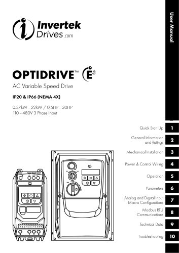 E3 IP66 Indoor User Guide
40 Pages
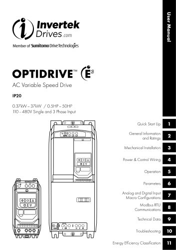 E3 IP20 User Guide
40 Pages
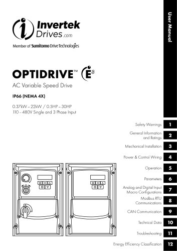 E3 IP66 Outdoor User Guide
58 Pages
 E3 IP66 Quick Start Guide
20 Pages
- Frequency inverter
- 3-phase frequency converter
- Compact frequency inverter
- Digital output frequency inverter
- IP20 frequency inverter
- Motor frequency converter
- Single-phase frequency inverter
- Vector control frequency inverter
- Industrial frequency inverter
- Variable-speed drive AC
- Fieldbus frequency inverter
- Integration frequency inverter
- Induction frequency converter
- Pump frequency inverter
- Wall-mounted frequency inverter
- Fan frequency converter
- Variable-frequency frequency inverter
- Vector-controlled frequency inverter
- Digital display frequency inverter
- Modbus frequency inverter