
- Catalogs
- Invertek Drives Ltd.
- E3 IP66 Quick Start Guide


- Products
- Catalogs
- News & Trends
- Exhibitions
E3 IP66 Quick Start Guide
1 /20Pages
E3 IP66 Quick Start Guide
1 /20Pages
Catalog excerpts

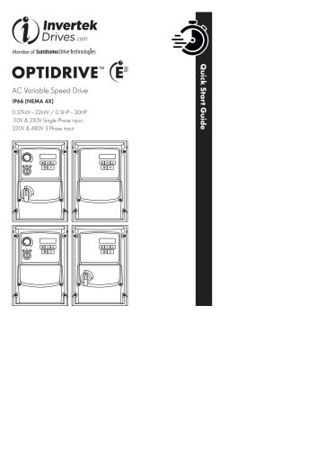
InvertekDrives c om Member of Sumitomo Drive Technologies AC Variable Speed Drive IP66 (NEMA4X)
Open the catalog to page 1
Please scan the QR code to access the complete User Manual □ CHECK: Check the correct drive type, check suitable motor type & info 0 PREPARE: Correct tools, suitable mounting location, weather protection 0 MOUNT: Mechanical mounting Q CONNECT: Power & Control connections 0 CHECK: Final check of everything before operation □ COMMISSION the drive parameters 0 OPERATE and check everything is as intended NOTE This guide does not provide detailed installation, safety or operational instructions. See the Optidrive E3 IP66 Outdoor User Manual for complete information. Unpack and check the drive. Notify...
Open the catalog to page 2
Prepare the Mounting Location ■ The Optidrive must be mounted in a vertical position only. ■ Installation should be on a suitable flat, flame resistant surface. Do not mount flammable material close to the drive. ■ Refer to Technical Data and ensure the chosen mounting location is within the drive specification. ■ The mounting location should be free from vibration. ■ Do not mount the drive in any area with excessive humidity, corrosive airborne chemicals or potentially dangerous dust particles. ■ Avoid mounting close to high heat sources. ■ The drive must not be mounted in direct sunlight. If...
Open the catalog to page 3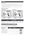
Cable Selection ■ For 1 phase supply (Sizes 1 -3 only), the mains power cables should be connected to LI /L, L2/N. ■ For 3 phase supplies, the mains power cables should be connected to LI, L2, and L3. Phase sequence is not important. ■ For compliance with CE and C Tick EMC requirements, refer to online documentation. ■ A fixed installation is required according to IEC61800-5-1 with a suitable disconnecting device installed between the Optidrive and the AC Power Source. The disconnecting device must conform to the local safety code / regulations (e.g. within Europe, EN60204-1, Safety of machinery)....
Open the catalog to page 4
Opfidrive E3 is designed to meet the UL requirements. For an up to date list of UL compliant products, please refer to UL listing NMMS.E226333. In order to ensure full compliance, the following must be fully observed. Input Power Supply Requirements Mechanical Installation Requirements All Optidrive E3 units are intended for installation within controlled environments which meet the condition limits shown in the Environment section of this Quick Start Guide. The drive can be operated within an ambient temperature range as stated in the Environment section of this Quick Start Guide. Incoming power...
Open the catalog to page 5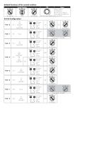
Switch Configuration
Open the catalog to page 6
Serial RS485 Port Ethernet Ports (Factory fit option) Control Terminals ■ All analog signal cables should be suitably shielded. Twisted pair cables are recommended. ■ Power and Control Signal cables should be routed separately where possible, and must not be routed parallel to each other. ■ Signal levels of different voltages e.g. 24 Volt DC and 110 Volt AC, should not be routed in the same cable. ■ Maximum control terminal tightening torque is 0.5Nm. ■ Control Cable entry conductor size: 0.05 - 2.5mm2 / Control Switched Units: May use the built in control switch and potentiometer, or external...
Open the catalog to page 7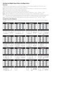
Optidrive E3 uses a Macro approach to simplify the configuration of the Analog and Digital Inputs. There are two key parameters which determine the input functions and drive behaviour: P-12 Selects the main drive control source and determines how the output frequency of the drive is primarily controlled. P-15 Assigns the Macro function to the analog and digital inputs. Additional parameters can then be used to further adapt the settings, e.g. P-16 Used to select the format of the analog signal to be connected to analog input 1, e.g. 0-10 Volt, 4 - 20mA. P-30 Determines whether the drive should...
Open the catalog to page 8
START FWD O STOP START REV O Fire Mode Fire Mode Fire Mode Fire Mode
Open the catalog to page 10
Macro Functions - Keypad Mode (P-12 = 1 or 2)
Open the catalog to page 11
Macro Functions - User PI Control Mode (P-12 = 5 or 6) Compatible Thermistor: PTC Type, 2.5kQ trip level. ■ Use a setting of P-15 that has Input 3 function as External Trip, e.g. P-15 - 3. Refer to online documentation for further details. ■Set P-47 = "Ptc-th"
Open the catalog to page 12
Operation Managing the Keypad The drive is configured and its operation monitored via the keypad and display.
Open the catalog to page 13
Parameters Standard Parameters
Open the catalog to page 14
Asynchronous Induction Motors (IM) Vector Control Optidrive E3 factory default parameters are intended for use with IM motors where the power rating of the motor is approximately the same or slightly less than the indicated power rating of the drive. In this case, it should be possible to operate the motor without any parameter adjustment at all for initial testing. For optimum performance, the drive parameters should be adjusted to match the motor ratings. This will also ensure correct protection of the motor from damage due to overload. The basic parameters that should be adjusted are: ■ P-07...
Open the catalog to page 17
NOTE Cable sizes shown are the maximum possible that may be connected to the drive. Cables should be selected according to local wiring codes or regulations at the point of installation.
Open the catalog to page 18
NOTE Following an over current or overload trip (1, 3, 4, 15], the drive may not be reset until the reset time delay has elapsed to prevent damage to the drive. Invertek Drives Ltd. Offa's Dyke Business Park, Welshpool, Powys SY21 8JF United Kingdom Tel: +44 (0) 1938 556868 Fax: +44 (0) 1938 556869
Open the catalog to page 20All Invertek Drives Ltd. catalogs and technical brochures
 Fieldbus User Guide
62 Pages
 E3 IP66 Indoor User Guide
40 Pages
 E3 IP20 User Guide
40 Pages
 E3 IP66 Outdoor User Guide
58 Pages
- Frequency inverter
- 3-phase frequency converter
- Compact frequency inverter
- Digital output frequency inverter
- IP20 frequency inverter
- Motor frequency converter
- Single-phase frequency inverter
- Vector control frequency inverter
- Industrial frequency inverter
- Variable-speed drive AC
- Fieldbus frequency inverter
- Integration frequency inverter
- Induction frequency converter
- Pump frequency inverter
- Wall-mounted frequency inverter
- Fan frequency converter
- Variable-frequency frequency inverter
- Vector-controlled frequency inverter
- Digital display frequency inverter
- Modbus frequency inverter