
- Catalogs
- Invertek Drives Ltd.
- E3 IP66 Indoor User Guide


- Products
- Catalogs
- News & Trends
- Exhibitions
E3 IP66 Indoor User Guide
1 /40Pages
E3 IP66 Indoor User Guide
1 /40Pages
Catalog excerpts

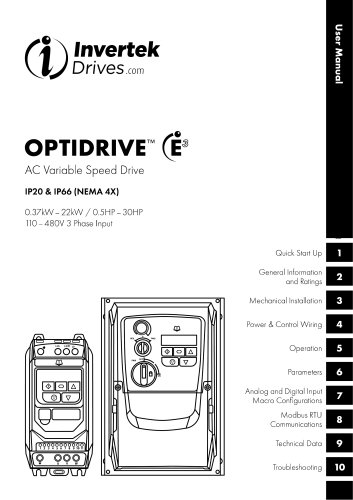
InyertekDrivGS .com User Manual OPTIDRIVE (EAC Variable Speed DriveIP20&IP66 (NEMA4X)0.37kW - 22 kW / 0.5HP - 30HP 110-480V 3 Phase Input General Information and Ratings Mechanical Installation Power & Control Wiring Operation Analog and Digital Input Macro Configurations Technical Data Troubleshooting
Open the catalog to page 1
3.3. Mechanical Dimensions and Mounting - IP20 Open Units .. 3.5. Mechanical Dimensions - IP66 (Nema 4X) Enclosed Units .. 4. Z Using the REV/O/FWD Selector Switch (Switched Version 7. Analog and Digital Input Macro Configurations.. .31 Z5. Macro Functions - Fieldbus Control Mode (P-12 = 3,4,7, 8 Z6. Macro Functions - User PI Control Mode (P-12 = 5 or 6) .. 34 2 | Optidrive ODE-3 User Guide
Open the catalog to page 2
Invertek Drives Ltd hereby states that the Optidrive ODE-3 product range conforms to the relevant safety provisions of the following council directives: Designed and manufacture is in accordance with the following harmonised European standards: Version 2.00 | Optidrive ODE-3 User Guide | 3
Open the catalog to page 3
Please read the IMPORTANT SAFETY INFORMATION below, and all Warning and Caution information elsewhere. A Danger: Indicates a risk of electric shock, which, /(/\ if not avoided, could result in damage to the / * \ equipment and possible injury or death. This variable speed drive product (Optidrive) is intended for professional incorporation into complete equipment or systems as part of a fixed installation. If installed incorrectly it may present a safety hazard. The Optidrive uses high voltages and currents, carries a high level of stored electrical energy, and is used to control mechanical plant...
Open the catalog to page 4
1.2. Quick Start Process 1.3. Installation Following a Period of Storage If the drive has not been powered, either unused or in storage, the DC Link Capacitors require reforming before power may be connected to the drive. Refer to your local sales partner for information regarding the correct procedure. Quick Start Up www.mvertekdrives.com Version 2.00 | Optidrive ODE-3 User Guide | 5
Open the catalog to page 5
1.4. Quick Start OverviewQuick Start - IP20 & IP66 Non Switched ■ Connect a Start / Stop switch between control terminals 1 & 2 o Close the Switch to Start o Open to Stop ■ Connect a potentiometer (5k - lOkQ) between terminals 5, 6 and 7 as shown o Adjust the potentiometer to vary the speed from P-02 (OHz default) to P-01 (50 / 60 Hz default) Switch the mains power on to the unit using the built in isolator switch on the front panel. The OFF/REV/FWD will enable the output and control the direction of rotation of the motor. The potentiometer will control the motor shaft rotational speed. 6 | Optidrive...
Open the catalog to page 6
This chapter contains information about the Optidrive E3 including how to identify the drive. Each drive can be identified by its model number, as shown in the table below. The model number is on the shipping label and the drive nameplate. The model number includes the drive and any options. 2.2. Drive Model Numbers no General Information and Ratings www.mvertekdrives.com Version 2.00 | Optidrive ODE-3 User Guide | 7
Open the catalog to page 7
Optidrive ODE-3 User Guide
Open the catalog to page 8
■ The Optidrive should be mounted in a vertical position only, on a flat, flame resistant, vibration free mounting using the integral mounting holes or DIN Rail clip (Frame Sizes 1 and 2 only). ■ IP20 Optidrives must be installed in a pollution degree 1 or 2 environment only. ■ Do not mount flammable material close to the Optidrive. ■ Ensure that the minimum cooling air gaps, as detailed in section 3.5. Mechanical Dimensions - IP66 (Nema 4X) Enclosed Units and 3.Z Gland Plate and Lock Off are left clear. ■ Ensure that the ambient temperature range does not exceed the permissible limits for the...
Open the catalog to page 9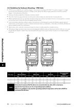
3.4. Guidelines for Enclosure Mounting - IP20 Units ■ IP20 drives are suitable for use in pollution degree 1 environments, according to IEC-664-1. For pollution degree 2 or higher environments, drives should be mounted in a suitable control cabinet with sufficient ingress protection to maintain a pollution degree 1 environment around the drive. ■ Enclosures should be made from a thermally conductive material. ■ Ensure the minimum air gap clearances around the drive as shown below are observed when mounting the drive. ■ Where ventilated enclosures are used, there should be venting above the drive...
Open the catalog to page 10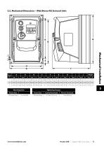
3.5. Mechanical Dimensions - IP66 (Nema 4X) Enclosed Units Mechanical Installation Tightening Torques Optidrive ODE-3 User Guide
Open the catalog to page 11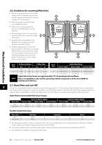
3.6. Guidelines for mounting (IP66 Units) ■ Before mounting the drive, ensure that the chosen location meets the environmental condition requirements for the drive shown in section 9.1. Environmental. ■ The drive must be mounted vertically, on a suitable flat surface. ■ The minimum mounting clearances as shown in the table below must be observed. ■ The mounting site and chosen mountings should be sufficient to support the weight of the drives. ■ Using the drive as a template, or the dimensions shown above, mark the locations required for drilling. ■ Suitable cable glands to maintain the ingress...
Open the catalog to page 12
Power Isolator Lock Off On the switched models the main power isolator switch can be locked in the 'Off' position using a 20mm standard shackle padlock (not supplied). IP66 / Nema 4X Unit Lock OffIP66 / Nema 4X Units Removing the 2 screws on the front of the product allows access to the connection terminals, as shown below. Mechanical Installation 3.9. Routine Maintenance The drive should be included within the scheduled maintenance program so that the installation maintains a suitable operating environment, this should include: ■ Ambient temperature is at or below that set out in section 9.1....
Open the catalog to page 13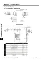
4. Power & Control Wiring 4.1. Connection Diagram 4.1.2. IP66 (Nema 4X) Switched Units 14 | Optidrive ODE-3 User Guide | Version 2.00
Open the catalog to page 14
4.2. Protective Earth (PE) ConnectionGrounding Guidelines The ground terminal of each Optidrive should be individually connected DIRECTLY to the site ground bus bar (through the filter if installed). Optidrive ground connections should not loop from one drive to another, or to, or from any other equipment. Ground loop impedance must confirm to local industrial safety regulations. To meet UL regulations, UL approved ring crimp terminals should be used for all ground wiring connections. The drive Safety Ground must be connected to system ground. Ground impedance must conform to the requirements...
Open the catalog to page 15All Invertek Drives Ltd. catalogs and technical brochures
 Fieldbus User Guide
62 Pages
 E3 IP20 User Guide
40 Pages
 E3 IP66 Outdoor User Guide
58 Pages
 E3 IP66 Quick Start Guide
20 Pages
- Frequency inverter
- 3-phase frequency converter
- Compact frequency inverter
- Digital output frequency inverter
- IP20 frequency inverter
- Motor frequency converter
- Single-phase frequency inverter
- Vector control frequency inverter
- Industrial frequency inverter
- Variable-speed drive AC
- Fieldbus frequency inverter
- Integration frequency inverter
- Induction frequency converter
- Pump frequency inverter
- Wall-mounted frequency inverter
- Fan frequency converter
- Variable-frequency frequency inverter
- Vector-controlled frequency inverter
- Digital display frequency inverter
- Modbus frequency inverter