
- Catalogs
- Invertek Drives Ltd.
- E3 IP20 User Guide


- Products
- Catalogs
- News & Trends
- Exhibitions
E3 IP20 User Guide
1 /40Pages
E3 IP20 User Guide
1 /40Pages
Catalog excerpts

InyertekDrivGS .com User Manual Member of Sumitomo DriveTechnologies AC Variable Speed Drive IP20 110-480V Single and 3 Phase Input Analog and Digital Input Macro Configurations Technical Data Troubleshooting Energy Efficiency Classification
Open the catalog to page 1
3.3. Mechanical Dimensions and Mounting - IP20 Open Units .. 7. Analog and Digital Input Macro Configurations.. .27 76. Macro Functions - Fieldbus Control Mode (P-12 = 3, 4, 7, 2 | Optidrive ODE-3 User Guide
Open the catalog to page 2
It is the responsibility of the installer to ensure that the equipment or system into which the product is incorporated complies with all relevant legislation and codes of practice which apply in the country of use. All Invertek Drives products intended for use within the European Union carry the CE mark to indicate compliance with European Directives. A declaration of conformity is available from the website, www.invertekdrives.com For compliance with the European EMC Directive, the necessary guidance is provided within this document and it is the responsibility of the installer to ensure this...
Open the catalog to page 3
Please read the IMPORTANT SAFETY INFORMATION below, and all Warning and Caution information elsewhere. A Danger: Indicates a risk of electric shock, which, /(/\ if not avoided, could result in damage to the / * \ equipment and possible injury or death. This variable speed drive product (Optidrive) is intended for professional incorporation into complete equipment or systems as part of a fixed installation. If installed incorrectly it may present a safety hazard. The Optidrive uses high voltages and currents, carries a high level of stored electrical energy, and is used to control mechanical plant...
Open the catalog to page 4
1.2. Quick Start Process Quick Start Up www.mvertekdrives.com Version 1.05 | Optidrive ODE-3 User Guide
Open the catalog to page 5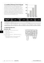
Where the drive has been stored for some time prior to installation, or has remained without the main power supply present for an extended period of time, it is necessary to reform the DC capacitors within the drive according to the following table before operation. For drives which have not been connected to the main power supply for a period of more than 2 years, this requires a reduced mains voltage mains voltage to be applied for a time period, and gradually increased prior to operating the drive. The voltage levels relative to the drive rated voltage, and the time periods for which they...
Open the catalog to page 6
Product Family Generation Frame Size No. Of Input Phases Output Current x 10 2. General Information and Ratings This chapter contains information about the Optidrive E3 including how to identify the drive. Each drive can be identified by its model number, as shown in the table below. The model number is on the shipping label and the drive nameplate. The model number includes the drive and any options. Dynamic Brake 1 = Not Fitted Transistor 4 = Internal Transistor Filter Type 0 = No Filter Version 1.05 | Optidrive ODE-3 User Guide | 7 General Information and Ratings
Open the catalog to page 7
Optidrive ODE-3 User Guide | Version 1.05
Open the catalog to page 8
■ The Optidrive should be mounted in a vertical position only, on a flat, flame resistant, vibration free mounting using the integral mounting holes or DIN Rail clip (Frame Sizes 1 and 2 only). ■ IP20 Optidrives are designed to be installed in suitable enclosures to protect them from the environment. ■ Do not mount flammable material close to the Optidrive. ■ Ensure that the ambient temperature range does not exceed the permissible limits for the Optidrive given in section 9.1. Environmental on page 36. ■ Provide suitable clean, moisture and contaminant free cooling air sufficient to fulfil the...
Open the catalog to page 9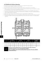
3.4. Guidelines for Enclosure Mounting ■ IP20 drives are are designed to be installed in suitable enclosures to protect them from the environment. ■ Enclosures should be made from a thermally conductive material. ■ Ensure the minimum air gap clearances around the drive as shown below are observed when mounting the drive. ■ Where ventilated enclosures are used, there should be venting above the drive and below the drive to ensure good air circulation. Air should be drawn in below the drive and expelled above the drive. ■ In any environments where the conditions require it, the enclosure must be...
Open the catalog to page 10
4.2. Protective Earth (PE) Connection Grounding Guidelines The ground terminal of each Optidrive should be individually connected DIRECTLY to the site ground bus bar (through the filter if installed). Optidrive ground connections should not loop from one drive to another, or to, or from any other equipment. Ground loop impedance must confirm to local industrial safety regulations. To meet UL regulations, UL approved ring crimp terminals should be used for all ground wiring connections. The drive Safety Ground must be connected to system ground. Ground impedance must conform to the requirements...
Open the catalog to page 11
Power & Control Wiring Shield Termination (Cable Screen) The safety ground terminal provides a grounding point for the motor cable shield. The motor cable shield connected to this terminal (drive end) should also be connected to the motor frame (motor end). Use a shield terminating or EMI clamp to connect the shield to the safety ground terminal. ■ For 1 phase supply, the mains power cables should be connected to LI /L, L2/N. ■ For 3 phase supplies, the mains power cables should be connected to LI, L2, and L3. Phase sequence is not important. ■ For compliance with CE and C Tick EMC requirements,...
Open the catalog to page 12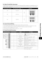
4.5. Motor Terminal Box Connections Most general purpose motors are wound for operation on dual voltage supplies. This is indicated on the nameplate of the motor. This operational voltage is normally selected when installing the motor by selecting either STAR or DELTA connection. STAR always gives the higher of the two voltage ratings. Version 1.05 | Optidrive ODE-3 User Guide | 13 Power & Control Wiring
Open the catalog to page 13
Power & Control Wiring The analog output function may be configured using parameter P-25, which is described in section 6.2. Extended Parameters on page 20. The output has two operating modes, dependent on the parameter selection: o The output is a 0 - 10 volt DC signal, 20mA max load current. o The output is 24 volt DC, 20mA max load current. The relay output function may be configured using parameter P-18, which is described in section 6.2. Extended Parameters on page 20. Two analog inputs are available, which may also be used as Digital Inputs if required. The signal formats are selected by...
Open the catalog to page 14All Invertek Drives Ltd. catalogs and technical brochures
 Fieldbus User Guide
62 Pages
 E3 IP66 Indoor User Guide
40 Pages
 E3 IP66 Outdoor User Guide
58 Pages
 E3 IP66 Quick Start Guide
20 Pages
- Frequency inverter
- 3-phase frequency converter
- Compact frequency inverter
- Digital output frequency inverter
- IP20 frequency inverter
- Motor frequency converter
- Single-phase frequency inverter
- Vector control frequency inverter
- Industrial frequency inverter
- Variable-speed drive AC
- Fieldbus frequency inverter
- Integration frequency inverter
- Induction frequency converter
- Pump frequency inverter
- Wall-mounted frequency inverter
- Fan frequency converter
- Variable-frequency frequency inverter
- Vector-controlled frequency inverter
- Digital display frequency inverter
- Modbus frequency inverter