KNX-DALI Gateway
1 /3Pages
KNX-DALI Gateway
1 /3Pages
Catalog excerpts
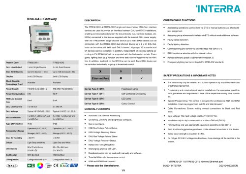
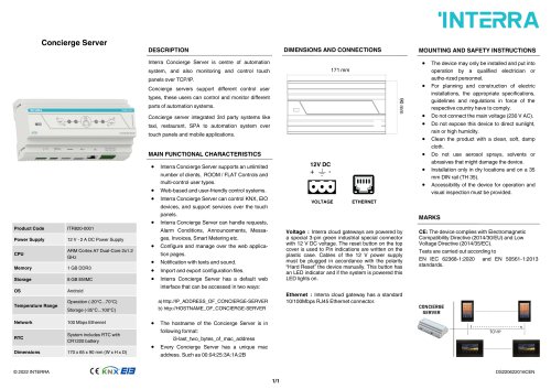
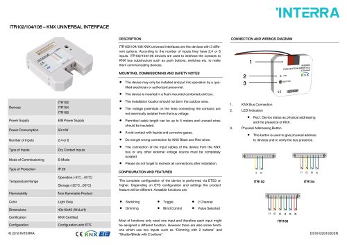
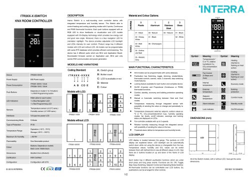
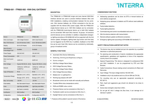
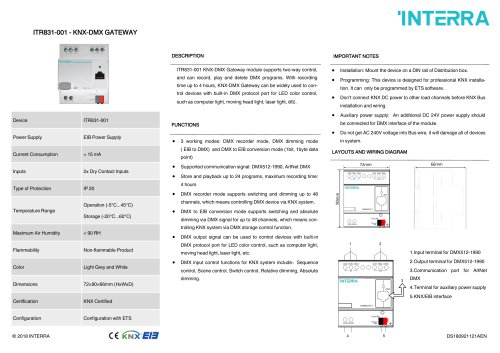
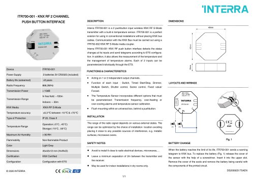
DESCRIPTION COMISSIONING FUNCTIONS Product Code DALI Line Output Max. ECG Devices Display Short-Circuit & Overvoltage Proof Power Supply Power Consumption DALI Line Current DALI Voltage Temperature Range 1 x 64, Single Channel 2 x 64, Dual Channel Up to 64 devices (1 x 64) Up to 128 devices (2 x 64) 2x16 LCD Display 2x16 LCD Display Available Available Light Grey and White Light Grey and White Configuration with ETS Configuration with ETS The ITR832-00X1 & ITR832-00X2 single and dual-channel KNX-DALI interface devices are used to provide an interface between DALI and KNX installations, enabling communication between the two protocols. DALI devices (ballasts, etc. ECGs) connected to the line are supplied with the internal DALI power supply. With the ITR832-00X1 single-channel device up to 1x64 DALI ballasts can be connected, with the ITR832-00X2 dual-channel device up to 2 x 64 DALI ballasts can be connected. With each DALI channel, 16 groups, 16 scenarios and 64 devices can be controlled. In addition, independent emergency lighting according to EN 62386-202 will be supported with the 2nd version update. Emergency lighting tests (e.g. function and time test) can be triggered via the KNX line. In addition, feedback on the KNX line can be sent. Each DALI device can be controlled individually, in group or broadcast control. • Addressing operations can be done via ETS or manual buttons as a short address assignment. • Assigning group adressess to ballasts via ETS without need additional software. • Faulty ballast detection. • Faulty lighting detection. • Commissioning and control via an embedded web server (**). • DALI line device selection with the manual button. • Remote software update via Ethernet connection.(*) • Emergency lighting test (according to EN 62386-202 standard). Device Type 0 (DT0) Fluorescent Lamp Device Type 1 (DT1) Self-Contained Emergency Device Type 6 (DT6) LED Lamp Device Type 8 (DT8) Colour Control • Automatic DALI Device Addressing. • Switching, Dimming and Brightness configure. • Scene configure. • KNX Bus Voltage Failure Status. • KNX Voltage Recovery Status. • DALI Bus Voltage Failure Status. • DALI Voltage Recovery Status. • Ballast and / or Lighting Error. • Working log analysis with UDP. • Broadcast control can be made with manually and software. • T unable White color temperature control. • RGB and RGBW color control. SAFETY PRECAUTIONS & IMPORTANT NOTES • The device may only be installed and put into operation by a qualified electrician or authorized personnel. • For planning and construction of electric installations, the appropriate specifications, guidelines and regulations in force of the respective country have to comply. • Special Programming: This device is designed for professional KNX and DALI installation. It can be programmed by ETS and Web Browser*. • Cable Connections: Ensure making correct connections for Black and Red wires. • Input Voltage: The input voltage shall be 110-240 V AC. • Installation only in dry locations and on a 35 mm DIN rail (TH 35). • For mounting, only use appropriate equipment according to IEC 60715. • Rain, liquid and aggressive gas should not be allowed to be close to the device. • Screw down strength is less than 0.4 Nm. • Do not get AC 240 V voltage into Bus lines, it can damage all the devices in the system. * : ITR832-0011 & ITR832-0012 have no Ethernet port © 2024 INTERRA &nb
Open the catalog to page 1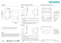
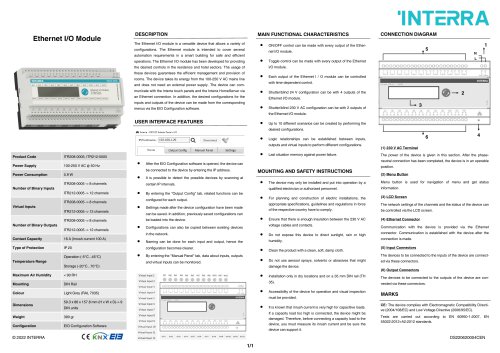
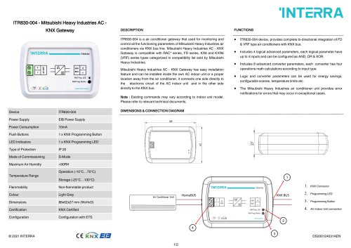
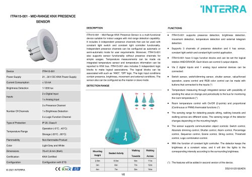
MOUNTING & DEMOUNTING PROCESSES INTERRAFEATURES OF CONNECTORS & BUTTONS • First, the device is contacted to the DIN rail by holding it at an oblique angle. • Then, it is pushed slightly from above in the direction of the 1st numbered arrow. • Finally, the device is pushed slightly in the direction of the 2nd arrow and placed on the DIN rail to finish the mounting. • All values given in the device dimensions are in millimetres. • The device can be used in an area of up to 4 modules. MARKS CE: Interra KNX-DALI Gateway complies with Electromagnetic Compatibility Directive (2014/30/EU), Low Voltage...
Open the catalog to page 2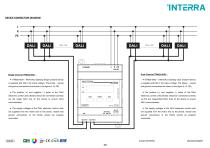
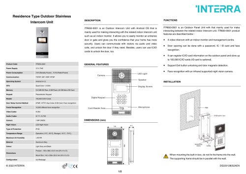
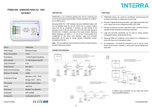
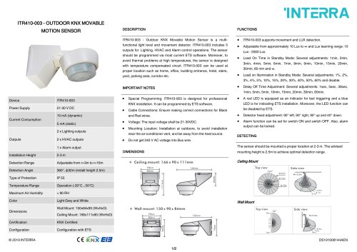
DEVICE CONNECTION DIAGRAM INTERRA DALI ■ DALI ETHERNET KNX-DALI GATEWAY KNXPROG BUSftSSi LED BUTTON _ + Single Channel ITR832-00X1 : • ITR832-00X1 - KNX-DALI Gateway Single Channel device is supplied with 240 V AC mains voltage. The phase, neutral and ground connections are shown in the figure (L, N, PE). • The positive (+) and negative (-) poles of the DALI electronic control units (ECGs) should be connected correctly via the single DALI line on the device to ensure DALI communication. • The supply voltages of the DALI electronic control units are supplied from the mains and so the phase, neutral...
Open the catalog to page 3All Interra catalogs and technical brochures
 Concierge Server
1 Page
 Ethernet I/O Module
1 Page
Archived catalogs
 itr10
itr101 Page
 itr901
1 Page
 itr230
3 Pages
 itr640-001
2 Pages
 itr3
itr32 Pages


- Panel PC
- Industrial panel PC
- Panel PC with touch screen
- LCD panel PC
- LCD screen
- Monitor with touchscreen
- Digital I/O
- Panel-mount screen
- Single-pole switch
- IO module
- Wireless panel PC
- Analog I/O
- Digital IO module
- WiFi panel PC
- Communication gateway
- Industrial gateway
- Ethernet gateway
- TFT-LCD monitor
- Ethernet panel PC
- Ethernet communication router