ITR5XX SERIES KNX COMBO SWITCH ACTUATOR
1 /1Page

ITR5XX SERIES KNX COMBO SWITCH ACTUATOR
1 /1Page
Catalog excerpts

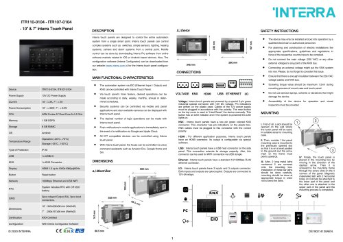
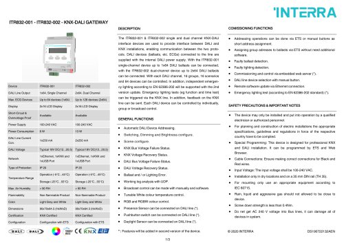
ITR5XX SERIES KNX COMBO SWITCH ACTUATOR MAIN FUNCTIONAL CHARACTERISTICS The combo switch actuator is a versatile device which allows a variety of configurations. The combo device is intended to cover every automation requirement in a smart building for safe and efficient operations. The communication of the devices via the KNX bus enables information exchanges with KNX sensors and the integration with a building management system. The combo has been developed for providing the whole controls in the residence and hotel sectors. The usage of this devices guarantees the efficient management and provision of rooms. The manual control of the outputs is possible through the push buttons on the device. It allows the control of the outputs when bus communication failures between devices occur. The combo actuator is supplied with power from the KNX and accordingly does not need any external power supply. The complete configuration of the device is performed via ETS. Type and number of the available objects Device Power Supply Current Consumption depend on the settings with ETS. Combo Output Module Family Commissioning Mode Lighting control can be made with every output of the combo switch actuator. Heating control can be made with every output of the combo switch actuator. Every output of the combo module can be configured as shutter/blind provided that 2 consecutive outputs are available. Shutter/blind 24V configuration can be with 4 outputs of the combo module. However, it is only available in the first four outputs of the (*) blocks. Output Current Temperature Range Non-flammable product Light Grey and White combo module. However, it is only available in the first five outputs of the (*) blocks. The functionalities for each output include among other things timing functions, logic gates, scenes, disabling function, forced, working hours counter, periodical monitoring and different configurations for feedback telegrams. Last situation memory against power failure. (*): Each block consists of every 6 outputs of the combo module that is starts from C1 output. (1) Physical Address Button This button is used to give a physical address to devices and to verify the bus presence. The red led switched on means the presence of KNX bus and the device status as physical addressing. MOUNTING AND SAFETY INSTRUCTIONS (2) Manual Control Button The device may only be installed and put into operation by a qualified electrician or authorized personnel. For planning and construction of electric installations the Do not connect the main voltage (230 VAC) or any other appropriate specifications, guidelines and regulations in force of the respective country have to be complied. external voltages to any point of the KNX bus. Combo Output Module Functionality Differences: Connecting an external voltage might put the KNX system into risk. Please, do not forget to consider this issue. Working Hours Counter Logic Gates Ensure that there is enough insulation between the 230 VAC voltage cables and KNX bus. Do not expose this device to direct sunlight, rain or high humidity. Clean the product with a clean, soft, damp cloth. Do not use aerosol sprays, solvents or abrasives that might Fan Coil 4 pipes configuration can be with 5 outputs of the combo module. However, it is only available in the first four outputs of the (*) blocks. Fan Coil 2 pipes configuration can be with 4 outputs of the Installation only in dry locations and on a 35 mm DIN rail (TH Via the push buttons present on the device, the loads connected to outputs can be controlled. This manual control has priority over the commands from the KNX bus. (3) Status LED The button LED indicates the status of the outputs. When the green LED is on, the output relays are closed. (4) KNX Connector The connection of the KNX bus line is made with the terminal block (block/red) included in delivery and inserted into the slot of housing. MARKS CE: The device complies with Electromagnetic Compatibility Directive (2004/108/EC) and Low Voltage Directive (2006/95/EC). Tests are carried out according to EN 60950-1:2007, EN 55022:2012+A2:2012 standards. Accessibility of the device for operation and visual inspec
Open the catalog to page 1All Interra catalogs and technical brochures
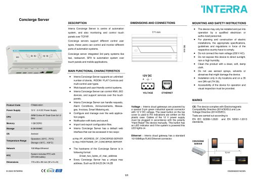 Concierge Server
1 Page
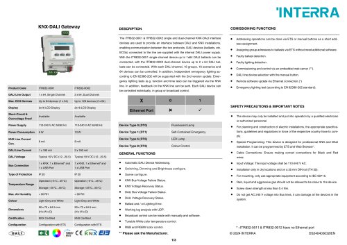 KNX-DALI Gateway
3 Pages
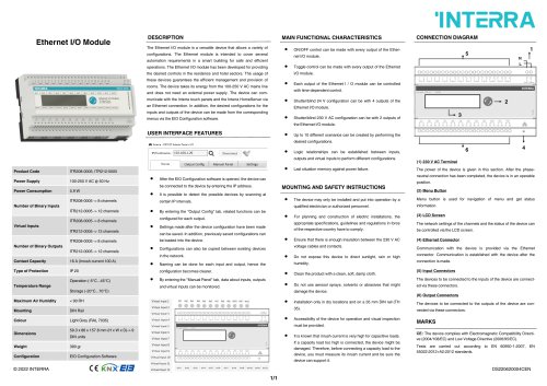 Ethernet I/O Module
1 Page
Archived catalogs
 itr10
itr101 Page
 itr901
1 Page
 itr230
3 Pages
 itr640-001
2 Pages
 itr3
itr32 Pages


- Panel PC
- Industrial panel PC
- Panel PC with touch screen
- LCD panel PC
- LCD screen
- Monitor with touchscreen
- Digital I/O
- Panel-mount screen
- Single-pole switch
- IO module
- Wireless panel PC
- Analog I/O
- Digital IO module
- WiFi panel PC
- Communication gateway
- Industrial gateway
- Ethernet gateway
- TFT-LCD monitor
- Ethernet panel PC
- Ethernet communication router