itr3
1 /2Pages

itr3
1 /2Pages
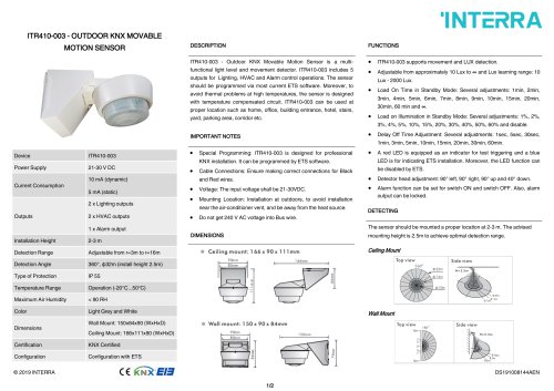
Catalog excerpts

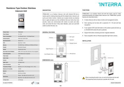
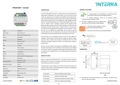
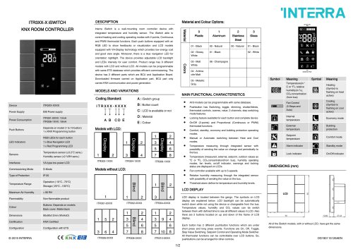
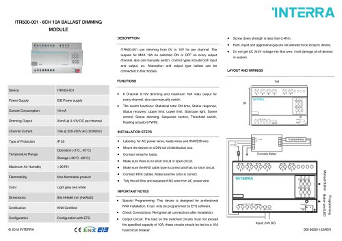
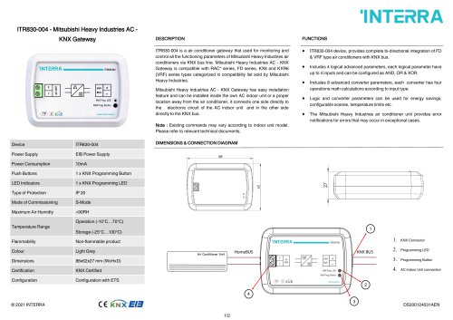
ITR3XX-X iSWITCH KNX ROOM CONTROLLER DESCRIPTION Interra iSwitch is a wall-mounting room controller device with integrated temperature and humidity sensor. The iSwitch able to control heating and cooling operating modes with 2-points, Continuous and PWM thermostat functions. Each push buttons equipped with an RGB LED to show feedbacks or visualization and LCD models equipped with VA-Display technology which provides low energy cost and good view angle. Moreover, there is a blue navigation LED for orientation nightlight. The device provides adjustable LCD backlight and LEDs intensity for user comfort. Product range has 9 different models with LCD and without LCD. All models can be programmable with same ETS database which provides efficient commissioning. The device has 2 different parts which are BCU and Application Board. Downloaded firmware carried on Application part, BCU part only carries KNX communication and power generation. MODELS AND VARIATIONS Material and Colour Options: MAIN FUNCTIONAL CHARACTERISTICS INTERRA Symbol Device Power Supply Power Consumption Push Buttons LED Indicators Sensors Interfaces Commissioning Mode Type of Protection Temperature Range Maximum Air Humidity Flammability Colour Dimensions Certification Configuration ITR3XX-XXXX EIB Power supply ITR301-0XXX: 10mA ITR308-1XXX: 18mA Depends on model (1 to 10 button) 1 x KNX Programming button RGB LEDs for each button 1 x Blue Navigation LED 1 x Red Programming LED Temperature sensor (±0.2°C sens.) Humidity sensor (±2 %RH sens.) VA-type low power LCD S-Mode IP 20 Operation (-10°C...70°C) Storage (-25°C...100°C) < 90 RH Non-flammable product Buttons: Depends on models Back cover: Matte black 90x90x12mm (WxHxD) KNX Certified Configuration with ETS Coding Standard: I T R 3 X X - X X X X IT III ABC D E Models with LCD: A : iSwitch group B : Button count C : LCD is available or not D : Material E : Colour 10 • All 9 models can be programmable with same database. • Pushbutton has Switching, toggle, dimming, shutter/blinds, thermostat controls, scenes, value, 2 channels, step switching mode features. • Locking feature available for each button and complete device • On/Off (2-points) and Proportional (Continuous or PWM) thermostat functions. • Comfort, standby, economy and building protection operating modes. • Manual or Automatic switching between Heat and Cool modes. • Temperature measuring through integrated sensor with possibility of sending the value on change and periodically to the bus. • Temperature (measured, external, setpoint, outdoor values as °C or °F), CO2 concentration(from bus), humidity operating modes, fan levels, on/off indicator, warnings and locking status are displayed on LCDs. • Fan controller available with up to 5-speeds. • Relative humidity measuring through the integrated sensor with possibility of sending the value on the bus. • Threshold alarm define for temperature and humidity levels. LCD DISPLAY Meaning Temperature(in ° C or °F), relative humidity(in %), CO2 concentration (from bus) Fan Control (5 Steps and Auto) Internal temperature External temperature Setpoint temperature Alarm indicator Lock indicator DIMENSIONS (mm) Symbol EHBaa Meaning Heating (Symbol is flashing on heat active) Cooling (Symbol is flashing on cool active) Economy mode Building protection Comfort mode Standby mode On/Off indicator LCD display is located between the gangs. The symbols on LCD display are explained below. LCD backlight can be automatically switch down while not using the device or changeable from the bus. Temperature values, humidity and CO2 values can be switch between them with defined time to see all different values in LCD. Also there are 2 buttons located on up and down of the frame of LCD display. Each button has 2 different pushbutton functions which are under short press and long press events. Functions are On, Off, Toggle, Step Value Switching, Setpoint Control and Operating Mode Switcher. All thermostat functions can be controllable over LCD buttons. So, pushbuttons can be arranged for other controls. All of the iSwitch models, with or without LCD, have got the same dimensions.
Open the catalog to page 1
The connection of the KNX bus line is made with the terminal block (black/red) included in delivery and inserted into the slot of housing. After pressing the buttons on the top left and bottom left corner of the device simultaneously, the programming LED is activated by pressing the button in the bottom right corner and LED’s red light is on. Also this can be done by pressing the programming button as another method. In the circumstances, the device is ready for programming. MOUNTING iSwitch’s mounting steps are described below. The procedures are described in 2 main sections : Mounting of BCU...
Open the catalog to page 2All Interra catalogs and technical brochures
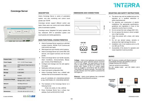 Concierge Server
1 Page
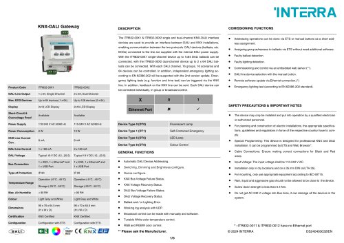 KNX-DALI Gateway
3 Pages
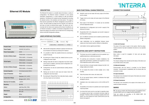 Ethernet I/O Module
1 Page
Archived catalogs
 itr10
itr101 Page
 itr901
1 Page
 itr230
3 Pages
 itr640-001
2 Pages


- Panel PC
- Industrial panel PC
- Panel PC with touch screen
- LCD panel PC
- LCD screen
- Monitor with touchscreen
- Digital I/O
- Panel-mount screen
- Single-pole switch
- IO module
- Wireless panel PC
- Analog I/O
- Digital IO module
- WiFi panel PC
- Communication gateway
- Industrial gateway
- Ethernet gateway
- TFT-LCD monitor
- Ethernet panel PC
- Ethernet communication router