Ethernet I/O Module
1 /1Page
Ethernet I/O Module
1 /1Page
Catalog excerpts

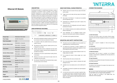
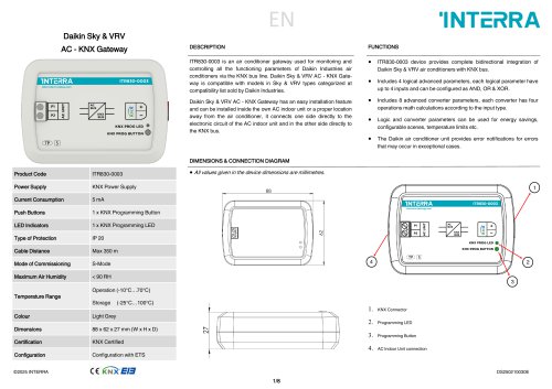
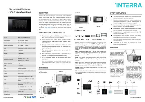
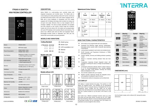
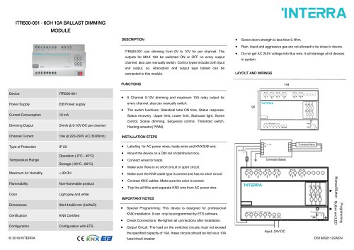
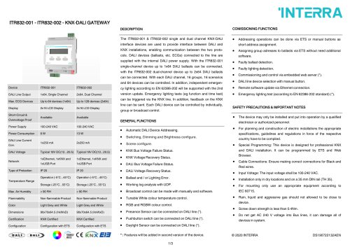
The Ethernet I/O module is a versatile device that allows a variety of configurations. The Ethernet module is intended to cover several automation requirements in a smart building for safe and efficient operations. The Ethernet I/O module has been developed for providing the desired controls in the residence and hotel sectors. The usage of these devices guarantees the efficient management and provision of rooms. The device takes its energy from the 100-250 V AC mains line and does not need an external power supply. The device can communicate with the Interra touch panels and the Interra HomeServer via an Ethernet connection. In addition, the desired configurations for the inputs and outputs of the device can be made from the corresponding menus via the EIO Configuration software. USER INTERFACE FEATURES MAIN FUNCTIONAL CHARACTERISTICS ON/OFF control can be made with every output of the Ethernet I/O module. Toggle control can be made with every output of the Ethernet I/O module. Each output of the Ethernet I / O module can be controlled with time-dependent control. Shutter/blind 24 V configuration can be with 4 outputs of the Ethernet I/O module. INTERRA CONNECTION DIAGRAM Hone Output Conflg Manual Panel Settings Product Code Power Supply Power Consumption Number of Binary Inputs Virtual Inputs Number of Binary Outputs Contact Capacity Type of Protection Temperature Range ITR208-0005 -> 8 channels ITR212-0005 -> 12 channels ITR208-0005 -> 8 channels ITR212-0005 -> 12 channels ITR208-0005 -> 8 channels ITR212-0005 -> 12 channels 16 A (Inrush current 100 A) Shutter/blind 230 V AC configuration can be with 2 outputs of the Ethernet I/O module. Up to 10 different scenarios can be created by performing the desired configurations. Logic relationships can be established between inputs, outputs and virtual inputs to perform different configurations. Last situation memory against power failure. After the EIO Configuration software is opened, the device can be connected to the device by entering the IP address. It is possible to detect the possible devices by scanning at certain IP intervals. MOUNTING AND SAFETY INSTRUCTIONS • By entering the "Output Config" tab, related functions can be configured for each output. • Settings made after the device configuration have been made can be saved. In addition, previously saved configurations can be loaded into the device. • Configurations can also be copied between existing devices in the network. • Naming can be done for each input and output, hence the configuration becomes clearer. • By entering the "Manual Panel" tab, data about inputs, outputs and virtual inputs can be monitored. • The device may only be installed and put into operation by a qualified electrician or authorized personnel. • For planning and construction of electric installations, the appropriate specifications, guidelines and regulations in force of the respective country have to comply. • Ensure that there is enough insulation between the 230 V AC voltage cables and contacts. • Do not expose this device to direct sunlight, rain or high humidity. Clean the product with a clean, soft, damp cloth. • Do not use aerosol sprays, solvents or abrasives that might damage the device. • Installation only in dry locations and on a 35 mm DIN rail (TH 35). • Accessibility of the device for operation and visual inspection must be provided. • It is known that inrush current is very high for capacitive loads. If a capacity load too high is connected, the device might be damaged. Therefore, before connecting a capacity load to the device, you must measure its inrush current and be sure the device can support it. The power of the device is given in this section. After the phase-neutral connection has been completed, the device is in an operable position. Menu button is used for navigation of menu and get status information. The network settings of the channels and the status of the device can be controlled via the LCD screen. Communication with the device is provided via the Ethernet connector. Communication is established with the device after the connection is made. The devices to be connected to the inputs of the device are connected via these connectors. The devices to be connected to the outputs of the device are connected via these connectors. CE: The device complies with Electromagnetic Compatibility Directive (2004/108/EC) and Low Voltage Directive (2006/95/EC). Tests are carried out according to EN 60950-1:2007, EN 55022:2012+A2:2012 standards.
Open the catalog to page 1All Interra catalogs and technical brochures
 Concierge Server
1 Page
 KNX-DALI Gateway
3 Pages
Archived catalogs
 itr10
itr101 Page
 itr901
1 Page
 itr230
3 Pages
 itr640-001
2 Pages
 itr3
itr32 Pages


- Panel PC
- Industrial panel PC
- Panel PC with touch screen
- LCD panel PC
- LCD screen
- Monitor with touchscreen
- Digital I/O
- Panel-mount screen
- Single-pole switch
- Wireless panel PC
- Analog I/O
- Digital IO module
- WiFi panel PC
- Communication gateway
- Industrial gateway
- Ethernet gateway
- TFT-LCD monitor
- Ethernet panel PC
- Ethernet communication router