- Catalogs
- Intellisense Microelectronics
- E3Z-F series
- Company
- Products
- Catalogs
- News & Trends
- Exhibitions
E3Z-F series
1 /2Pages

E3Z-F series
1 /2Pages
Catalog excerpts

INSTRUCTION MANUAL ! WARNING Thank you for selecting IMS product.This sheet primarily describes precautions required in installing and operating the product.Before operating the product,read the sheet thoroughly to acquire sufficient knowledge of the product.For your convenience,keep the sheet at your disposal. Failure to follow these instructions may result in serious injury or death: Fail-safe device must be installed when using the unit with machinery that may cause serious injury or substantial economic loss. (e.g. nuclear power control, medical equipment, ships, vehicles, railways, aircraft, combustion apparatus, safety equipment, crime/disaster prevention devices,etc.) Failure to follow these instructions may result in product damage: Do not use this unit over rated voltage; Do not use this unit where there is flammable or explosive gas; Do not use this unit where there is vibration or impact; In cleaning the unit, do not use water or an oil-based detergent. • High performance ASIC based advance sensor • Long product life time, 5us modulated pulse with 1/10 duty cycle reduced aging of LED • Build in 100ms power on delay, self-recover short circuit protection, reverse polarity, over voltage protection • Excellent noise immunity to DC light with modulated light source and CDS signal process technology • Mode selection for light on and dark on • Visible super bright red light for easy alignment • Distance adjustable using potentiometer C ■( Light source code) Connection type Response time_ Sensing method □ Operating timing diagram Operation mode Sensing distance unit Sensing distance ( slot series use 30/50 to refer slot distance ) | Numbed Sensing distance Sensing method ( slot series is none ) ^ The waveforms of”Operation indicator”and” Transistor output”are for Light on mode.
Open the catalog to page 1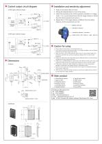
Control output circuit diagram Installation and sensitivity adjustment 1、Power on the sensor after it is fixed; NPN open collector output 2、Placing the detected object in front of the sensor ; 3、Adjust the sensitivity knob until the operation indication is in trigger mode (it is a normal phenomenon that the trigger distance is farther Main circuit Stability (green) Operation ( orange ) than the distance placed by the sensor); Over current protection 4、Repeat Step 3 if the trigger distance is different from the setting distance until the requirements are met. Stability indicator (C)White Control...
Open the catalog to page 2All Intellisense Microelectronics catalogs and technical brochures
 IMS liquid level sensor
2 Pages
 DSA
DSA1 Page
 CX6080 and EX6080 Series
2 Pages
 Label sensor LABS_O1700N
2 Pages
 Counting sensor DS series
2 Pages
 T18
T182 Pages
 PM Series
2 Pages
 SPX67 Series
2 Pages
 LD_outdoor sensor
2 Pages
 BA photoelectric sensor
2 Pages
 E3JM photoelectric sensor
2 Pages
 5 in1 digital tire guage
1 Page
 digital pressure gauge
1 Page
 E3Z-T photoelectric sensor
2 Pages
 light curtain
2 Pages
 Fork sensor BWL
2 Pages
 E3S50
E3S502 Pages
 E3S30
E3S302 Pages
 E3S15
E3S152 Pages
 E3S10
E3S102 Pages
 E3TA Series
2 Pages
 E3FA Series
2 Pages
 IMS product overview
8 Pages


- Level limit switch
- Pressure gauge
- Proximity switch
- Liquid level detector
- Level probe
- Liquid level sensor
- Inductive proximity sensor
- Analog level sensor
- Photoelectric sensor
- Stainless steel level detector
- Gas pressure gauge
- Digital output level sensor
- Threaded level switch
- Vessel level sensor
- Rectangular photoelectric sensor
- Distance sensor
- Liquid pressure gauge
- Plastic level switch
- Digital pressure gauge
- Light barrier