Intel® Ethernet Switch FM4000
1 /270Pages

Intel® Ethernet Switch FM4000
1 /270Pages
Catalog excerpts
Intel® Ethernet Switch FM4000 24-Port 10G Ethernet L2/L3/L4 Switch/Router Datasheet Networking Division (ND)
Open the catalog to page 1
LEGAL By using this document, in addition to any agreements you have with Intel, you accept the terms set forth below. You may not use or facilitate the use of this document in connection with any infringement or other legal analysis concerning Intel products described herein. You agree to grant Intel a non-exclusive, royalty-free license to any patent claim thereafter drafted which includes subject matter disclosed herein. INFORMATION IN THIS DOCUMENT IS PROVIDED IN CONNECTION WITH INTEL PRODUCTS. NO LICENSE, EXPRESS OR IMPLIED, BY ESTOPPEL OR OTHERWISE, TO ANY INTELLECTUAL PROPERTY RIGHTS IS...
Open the catalog to page 2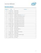
Revision History Revision General update. General Update. General update. Changed part number FM4104 to FM4105. General update (see revision document). General update (see revision document). General update (see revision document). General update (see revision document). General update (see revision document). General update (see revision document). General update (see revision document). General update. Formatting updates only. Added note preceding table in Section 16.5. General update. Update to Preliminary Datasheet. General update. General update (intermediate release). General update. First...
Open the catalog to page 3
This page intentionally left blank.
Open the catalog to page 4
This functional specification is the basis for the data sheet for the Intel® Ethernet Switch FM4000 series devices, and provides information on the significantly-enhanced feature set over the FM2000 series in the areas of routing, access control lists, congestion management, network scaling, and management. The FM4000 represents a family of products with various port configurations and package sizes, which This document pertains to all variants of the FM4000 platform, although most references are specific to the 24-port 10 GbE version of the device. The part marking and number conventions for...
Open the catalog to page 11
Key: • Prefix — “FM” identifies the device as an Intel Ethernet Switch Family product. • Product Family — Conveys information about the general capabilities of the device, as follows: 2 = FM2000 (L2) 3 = FM4000 with L2+ features 4 = FM4000 with full multi-layer feature set. • Port Configuration — Conveys information about the configuration of the ports on the device, as follows: 1 = Mostly single-SerDes interfaces (1 GbE, 2.5 GbE operation) 2 = Mostly quad-SerDes interfaces (10 GbE operation) • Aggregate Bandwidth — Identifies the approximate maximum bandwidth of the device configuration, calculated...
Open the catalog to page 12
• Section 3.0, “Pin Descriptions” • Section 4.0, “Ethernet Port Logic (EPL)” • Section 5.0, “Chip Management” • Section 6.0, “Filtering and Forwarding Unit (FFU)” • Section 7.0, “Routing” • Section 8.0, “Layer 2 Lookup” • Section 9.0, “Port Mapping and Packet Replication” • Section 10.0, “Frame Hashing” • Section 11.0, “Triggers” • Section 12.0, “QoS and Congestion Management” • Section 13.0, “Egress Scheduling and Shaping” • Section 14.0, “Statistics and Monitoring” • Section 15.0, “Electrical Specification” • Section 16.0, “Mechanical Specification” Terminology Definitions Denotes a bit concatenation...
Open the catalog to page 13
Terminology Definitions (Continued) Intel-proprietary Inter- Switch Link tag, which is used to pass relevant management and control information from one FM4000 device to another in a network. Jumbo Frame The maximum jumbo frame size for FM4xxx devices is 16,376 bytes. Logging refers to a copy of the frame sent to a local CPU for monitoring purpose. Mirroring refers to a copy of the frame sent to another port for monitoring purpose. Packet — On a typical computer network, data is transmitted in the form of structured and modest-sized packets. Instead of transmitting arbitrary-length strings of...
Open the catalog to page 14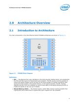
Architecture Overview The main components in the Intel Ethernet Switch FM4000 architecture are shown in Figure 2-1. Definitions: • EPL — The Ethernet Port Logic interfaces to the XAUI physical interface block, and implements the PCS and MAC layers for transmission and reception. The EPL parses incoming packets to extract the packet headers which are sent to the frame handler for packet processing while saving the entire packet in the shared memory. In the egress direction, the EPL receives segment pointers from the scheduler as well as extra data on the packet allowing the EPL to modify the packet...
Open the catalog to page 15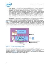
• Frame Handler — The frame handler makes forwarding decision on the packet based on the frame header received from the EPL. The forwarding information is sent to the scheduler. • Scheduler — The scheduler manages free data segments, maintains receive and transmit queues and schedules packets for transmission. The free segments are forwarded as needed to the EPLs which use them to store incoming packets to the right location in the shared memory fabric. The scheduler keeps the list of the segments sent to each EPL and waits for the frame handler forwarding decision before placing the packet at...
Open the catalog to page 16
Figure 2-3 FM4000 in a Stack Topology Figure 2-4 FM4000 in a Tightly-Coupled Clos Topology Figure 2-5 shows a fat-tree using non-Intel-tag-aware switches as spine switches. The loosely coupled architecture uses an F32 tag on internal links which is designed to be compatible with existing switches but only allows a subset of features to operate in this topology. The services not available in this architecture are distributed link aggregation and centralized management such as trapping and logging. Figure 2-5 FM4000 in a Loosely-Coupled Clos Architecture
Open the catalog to page 17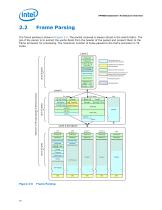
The frame parsing is shown in Figure 2-6. The packet received is always stored in the switch fabric. The job of the parser is to extract the useful fields from the header of the packet and present them to the frame processor for processing. The maximum number of bytes passed to the frame processor is 78 Other VLAN tags passed to frame processor. frame processor. Passed to frame processor Marks area that can optionally b passed to the frame processor for deep packet inspection Figure 2-6 Frame Parsing
Open the catalog to page 18All Intel catalogs and technical brochures
 10th Gen Intel® Core
7 Pages
 10th Gen
8 Pages
 nuc-celeron
4 Pages
 Intel® NUC 8 Home Mini PC
4 Pages
 Intel® Xeon® Scalable Platform
14 Pages
 Intel® Ethernet Controller XL710
1726 Pages
 Intel® Xeon® Processor E3-1200 v5
130 Pages
 Intel® Quark™ SoC X1000 Series
934 Pages
 Intel® X99 Chipset
4 Pages
 Intel® Desktop Board DQ67EP
4 Pages
 Intel® NUC Board DE3815TYBE
82 Pages
 S2600GZ and S2600GL
245 Pages
 i7-lga2011
314 Pages
 c600-series
936 Pages
 b75-express
4 Pages
 desktop-board
4 Pages
 3rd-gen-core-desktops
2 Pages
 /3rd-gen-core
2 Pages


Archived catalogs
 Intel® Ethernet Controllers
2 Pages
 Intel® 3450 Chipset
2 Pages
 Intel® 3000 and 3010 Chipset
4 Pages
 Intel® X58 Express Chipset
4 Pages
 Intel® Server Board S1200BT
8 Pages
 Intel® Desktop Board DX58SO2
4 Pages


- Bourn And Koch management software
- Bourn And Koch analysis software
- Bourn And Koch real-time software
- Bourn And Koch CAD software
- Bourn And Koch cloud software
- Bourn And Koch design software
- Bourn And Koch monitoring software
- Bourn And Koch interface software
- Visualization software solution
- Bourn And Koch simulation software
- Bourn And Koch programming software
- Development software
- Bourn And Koch network software
- Creation software
- Bourn And Koch optimization software
- Bourn And Koch test software
- Wireless module
- Bourn And Koch solid-state drive
- Bourn And Koch internal solid-state drive
- High-performance software