

Intel® Core™ i7-900 Desktop Processor Extreme Edition Series on 32-nm Process Datasheet, Volume 1

Intel® Core™ i7-900 Desktop Processor Extreme Edition Series on 32-nm Process Datasheet, Volume 1
This document provides comprehensive specifications for the Intel® Core™ i7-900 Desktop Processor Extreme Edition Series and the Intel® Core™ i7-900 Desktop Processor Series, manufactured using a 32-nm process. It covers electrical, mechanical, and thermal specifications, as well as features and boxed processor specifications.
The document details Intel® QuickPath Interconnect (QPI) differential signaling, power and ground lands, decoupling guidelines, processor clocking, and voltage identification (VID). It includes reserved or unused signals, signal groups, and test access port (TAP) connections. Platform environmental control interface (PECI) DC specifications, absolute maximum and minimum ratings, and processor DC specifications are also provided.
This section includes mechanical drawings, processor component keep-out zones, package loading specifications, handling guidelines, insertion specifications, processor mass, materials, markings, and land coordinates.
The thermal specifications section details package thermal specifications, thermal metrology, processor thermal features, and platform environment control interface (PECI). It includes fan speed control, thermal data sample rate, and filtering information.
The document describes power-on configuration, clock control, low power states, sleep states, ACPI P-states, and Enhanced Intel SpeedStep® Technology. It provides details on thread and core power state descriptions, package power state descriptions, and Intel® Turbo Boost Technology.
This section covers the mechanical specifications of the boxed processor, including cooling solution dimensions, fan heatsink weight, retention mechanism, and heatsink attach clip assembly. It also includes electrical requirements and thermal specifications for the boxed processor.
The document contains various figures illustrating processor interfaces, electrical characteristics, mechanical drawings, thermal profiles, and power states, aiding in understanding the detailed specifications and guidelines.
The processor core, Intel QPI, and integrated memory controller frequencies are derived from BCLK_DP and BCLK_DN. Maximum frequencies are set during manufacturing but can be overridden by software. The CLOCK_FLEX_MAX MSR can adjust the ratio for lower speeds.
VID signals set the reference voltage for the processor VCC pins and adjust due to temperature or current load changes. Individual processor VID values may vary, and the processor supports automatic voltage selection using VID[7:0].
An under-designed thermal solution can lead to excessive activation of the Thermal Control Circuit (TCC), causing performance loss. Proper design guidelines are essential to prevent these issues.
The document outlines storage conditions for Intel processors, specifying temperature and humidity limits to prevent damage. The storage temperature should be between -55°C and 125°C, while sustained storage should be between -5°C and 40°C with a maximum relative humidity of 60% at 24°C.
Configuration options for the processor are set during initialization and cannot be changed without a reset. These configurations are crucial for the processor's operation and are determined by hardware signals.
The document outlines the specifications for the fan power cable and connector used with a boxed processor. The fan requires a constant +12 V supply and does not support variable voltage control.
The document provides detailed specifications and guidelines for integrating the boxed processor fan heatsink into a system, emphasizing the importance of proper power supply, airflow management, and connection type for optimal performance and noise control.
Catalog excerpts

Document # 323252-002 Intel® Core™ i7-900 Desktop Processor Extreme Edition Series and Intel® Core™ i7-900 Desktop Processor Series on 32-nm Process Datasheet, Volume 1 July 2010
Open the catalog to page 1
2 Datasheet INFORMATION IN THIS DOCUMENT IS PROVIDED IN CONNECTION WITH INTEL PRODUCTS. NO LICENSE, EXPRESS OR IMPLIED, BY ESTOPPEL OR OTHERWISE, TO ANY INTELLECTUAL PROPERTY RIGHTS IS GRANTED BY THIS DOCUMENT. EXCEPT AS PROVIDED IN INTEL'S TERMS AND CONDITIONS OF SALE FOR SUCH PRODUCTS, INTEL ASSUMES NO LIABILITY WHATSOEVER, AND INTEL DISCLAIMS ANY EXPRESS OR IMPLIED WARRANTY, RELATING TO SALE AND/OR USE OF INTEL PRODUCTS INCLUDING LIABILITY OR WARRANTIES RELATING TO FITNESS FOR A PARTICULAR PURPOSE, MERCHANTABILITY, OR INFRINGEMENT OF ANY PATENT, COPYRIGHT OR OTHER INTELLECTUAL PROPERTY RIGHT....
Open the catalog to page 2
Datasheet 7 Revision History § Revision Number Description Date 001 • Initial release March 2010 002 • Added Intel® Core™ i7-970 desktop processor series July 2010
Open the catalog to page 7
Datasheet 9 Introduction 1 Introduction The Intel® Core™ i7-900 desktop processor Extreme Edition series and Intel® Core™ i7-900 desktop processor series on 32-nm process processor is intended for high performance, high-end desktop systems. Several architectural and microarchitectural enhancements have been added to this processor including six processor cores in the processor package and increased shared cache. The Intel® Core™ i7-900 desktop processor Extreme Edition series and and Intel® Core™ i7-970 desktop processor series on 32-nm process is a desktop multi-core processor with these key...
Open the catalog to page 9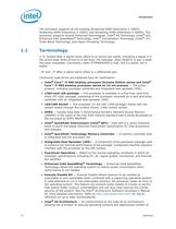
Introduction 10 Datasheet The processor supports all the existing Streaming SIMD Extensions 2 (SSE2), Streaming SIMD Extensions 3 (SSE3) and Streaming SIMD Extensions 4 (SSE4). The processor supports several Advanced Technologies: Intel® 64 Technology (Intel® 64), Enhanced Intel SpeedStep® Technology, Intel® Virtualization Technology (Intel® VT), Turbo Boost Technology, and Hyper-Threading Technology. 1.1 Terminology A ‘#’ symbol after a signal name refers to an active low signal, indicating a signal is in the active state when driven to a low level. For example, when RESET# is low, a reset has...
Open the catalog to page 10
Datasheet 13 Electrical Specifications 2 Electrical Specifications 2.1 Intel® QuickPath Interconnect (Intel® QPI) Differential Signaling The processor provides an Intel QPI port for high speed serial transfer between other Intel QPI-enabled components. The Intel QPI port consists of two unidirectional links (for transmit and receive). Intel QPI uses a differential signalling scheme where pairs of opposite-polarity (D_P, D_N) signals are used. On-die termination (ODT) provided on the processor silicon and termination is to VSS. Intel chipsets also provide ODT; thus, eliminating the need to terminate...
Open the catalog to page 13
Electrical Specifications 14 Datasheet condition from a running condition. Care must be taken in the baseboard design to ensure that the voltage provided to the processor remains within the specifications listed in Table 2-7. Failure to do so can result in timing violations or reduced lifetime of the processor. 2.3.1 VCC, VTTA, VTTD, VDDQ Decoupling Voltage regulator solutions need to provide bulk capacitance and the baseboard designer must assure a low interconnect resistance from the regulator to the LGA1366 socket. Bulk decoupling must be provided on the baseboard to handle large current swings....
Open the catalog to page 14
Datasheet 15 Electrical Specifications 2.5 Voltage Identification (VID) The Voltage Identification (VID) specification for the processor is defined by the Voltage Regulator Down (VRD) 11.1 Design Guidelines. The voltage set by the VID signals is the reference voltage regulator output voltage to be delivered to the processor VCC pins. VID signals are CMOS push/pull drivers. Refer to Table 2-15 for the DC specifications for these signals. The VID codes will change due to temperature and/or current load changes in order to minimize the power of the part. A voltage range is provided in Table 2-7....
Open the catalog to page 15
Electrical Specifications 18 Datasheet 2.6 Reserved or Unused Signals All Reserved (RSVD) signals must remain unconnected. Connection of these signals to VCC, VTTA, VTTD, VDDQ, VCCPLL, VSS, or to any other signal (including each other) can result in component malfunction or incompatibility with future processors. See Chapter 4 for a land listing of the processor and the location of all Reserved signals. For reliable operation, always connect unused inputs or bi-directional signals to an appropriate signal level, except for unused integrated memory controller inputs, outputs, and bi-directional...
Open the catalog to page 18
Datasheet 19 Electrical Specifications 2.7 Signal Groups Signals are grouped by buffer type and similar characteristics as listed in Table 2-3. The buffer type indicates which signaling technology and specifications apply to the signals. All the differential signals, and selected DDR3 and Control Sideband signals have On- Die Termination (ODT) resistors. There are some signals that do not have ODT and need to be terminated on the board. The signals that have ODT are listed in Table 2-4. Table 2-3. Signal Groups (Sheet 1 of 2) Signal Group Type Signals1,2 System Reference Clock Differential Clock...
Open the catalog to page 19
Electrical Specifications 20 Datasheet Note: 1. Unless otherwise specified, signals have ODT in the package with 50 Ă pulldown to VSS. 2. PREQ#, BPM[7:0], TDI, TMS and BCLK_ITP_D[N/P] have ODT in package with 35 Ă pullup to VTT. 3. VCCPWRGOOD, VDDPWRGOOD, and VTTPWRGOOD have ODT in package with a 10 kĂ to 20 kĂ pulldown to VSS. 4. TRST# has ODT in package with a 1 kĂ to 5 kĂ pullup to VTT. 5. All DDR signals are terminated to VDDQ/2 6. DDR{0/1/2} refers to DDR3 Channel 0, DDR3 Channel 1, and DDR3 Channel 2. 7. While TMS and TDI do not have On-Die Termination, these signals are weakly pulled...
Open the catalog to page 20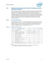
Datasheet 21 Electrical Specifications 2.9 Platform Environmental Control Interface (PECI) DC Specifications PECI is an Intel proprietary interface that provides a communication channel between Intel processors and chipset components to external thermal monitoring devices. The processor contains a Digital Thermal Sensor (DTS) that reports a relative die temperature as an offset from Thermal Control Circuit (TCC) activation temperature. Temperature sensors located throughout the die are implemented as analog-to-digital converters calibrated at the factory. PECI provides an interface for external...
Open the catalog to page 21All Intel catalogs and technical brochures
 10th Gen Intel® Core
7 Pages
 10th Gen
8 Pages
 nuc-celeron
4 Pages
 Intel® NUC 8 Home Mini PC
4 Pages
 Intel® Xeon® Scalable Platform
14 Pages
 Intel® Ethernet Controller XL710
1726 Pages
 Intel® Xeon® Processor E3-1200 v5
130 Pages
 Intel® Quark™ SoC X1000 Series
934 Pages
 Intel® X99 Chipset
4 Pages
 Intel® Desktop Board DQ67EP
4 Pages
 Intel® Ethernet Switch FM4000
270 Pages
 Intel® NUC Board DE3815TYBE
82 Pages
 S2600GZ and S2600GL
245 Pages
 i7-lga2011
314 Pages
 c600-series
936 Pages
 b75-express
4 Pages
 desktop-board
4 Pages
 3rd-gen-core-desktops
2 Pages
 /3rd-gen-core
2 Pages


Archived catalogs
 Intel® Ethernet Controllers
2 Pages
 Intel® 3450 Chipset
2 Pages
 Intel® 3000 and 3010 Chipset
4 Pages
 Intel® X58 Express Chipset
4 Pages
 Intel® Server Board S1200BT
8 Pages
 Intel® Desktop Board DX58SO2
4 Pages


- Management software solution
- Analysis software solution
- Real-time software
- Computer-aided design software
- Cloud-based software
- Design software solution
- Monitoring software solution
- Interface software
- Visualization software solution
- Simulation software solution
- Programming software
- Development software
- Network software
- Creation software
- Test software
- Optimization software
- Wireless module
- Solid-state drive
- Internal solid-state drive
- High-performance software