- Catalogs
- Integrated Visual Data Technology Inc
- SidWeigh OL Series
SidWeigh OL Series
1 /11Pages
SidWeigh OL Series
1 /11Pages
Catalog excerpts

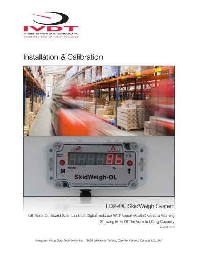
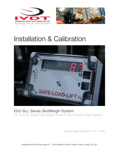
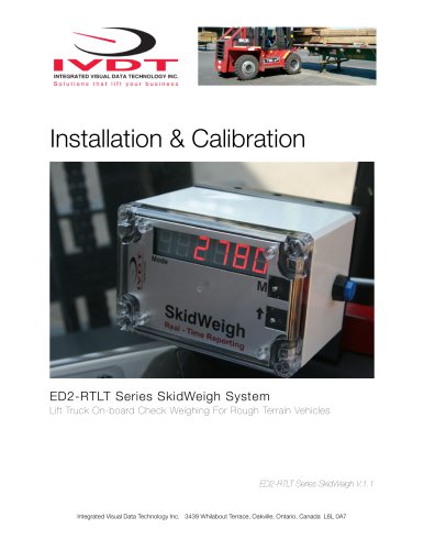
INTEGRATED VISUAL DATA TECHNOLOGY INC. Solutions that lift your business Installation & Calibration Lift Truck On-board Safe-Load-Lift Digital Indicator With Visual /Audio Overload Warning Showing In % Of The Vehicle Lifting Capacity Integrated Visual Data Technology Inc., 3439 Whilabout Terrace, Oakville, Ontario, Canada L6L 0A7
Open the catalog to page 1
General Installation Guide This ED2-OL SkidWeigh system installation & calibration guide describes how to install, calibrate, test and use your on-lift truck board load weighing system showing in % of vehicle lifting capacity. Following the instructions in this guide will enable you to get your system operating quickly and easily. In the event that you require additional assistance, please contact customer support via e-mail at [email protected] , visit www.skidweigh.com or contact us at the address or contact number below: Integrated Visual Data Technology Inc. 3439 Whilabout Terrace, Oakville,...
Open the catalog to page 2
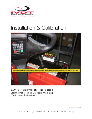
* Hydraulic pressure transducer with 3 wires cable * Installation & Calibration manual and operator usage instruction Operational principal The ED2-OL SkidWeigh system operational principal is based on the hydraulic pressure transducer mounted in the vehicle lifting hydraulic circuit that will automatically activate the “weighing cycle / specific algorithm ” every time a skid load is lifted just above the ground. The increase in pressure is converted in an electronic signal at the sample rate of 16000 readings per session which is converted into a load weight reading shown in % of vehicle lifting...
Open the catalog to page 3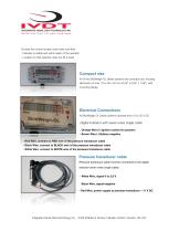
INTEGRATED VISUAL DATA TECHNOLOGY INC. Solutions that lift your business Choose the correct location and make sure that: - Indicator is visible and within reach of the operator - Location so that operator does not hit a head Compact size All of the SkidWeigh-OL Series systems are compact size, housing dimension of only 115 x 65 x 40 mm (4,53" x 2,65" x 1,58") with mounting flange. Electrical Connections All SkidWeigh OL Series systems operate from 12 to 55 V DC. Digital indicator with seven wires single cable - Orange Wire (+) Ignition switch On position ^ - Brown Wire (-) Battery negative -...
Open the catalog to page 4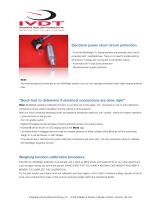
Electrical power short circuit protection - All of the SkidWeigh OL Series systems are internally short circuit protected with resettable fuse. There is no need to install external inline fuse in orange wire connected to the ignition switch. - Automotive 60 V load dump protection - Reversal power supply protection - Note: Any external devices connected to the SkidWeigh system, such as non standard onboard printer might require external fuse. “Quick test to determine if electrical connections are done right” Note: SkidWeigh weighing calibration function is not done yet at this stage. This procedure...
Open the catalog to page 5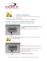
Calibration starting point Lower the empty forks to the ground. There should be no hydraulic pressure in lift hydraulic circuit. - Turn ignition switch to on position and start the engine - LED display will show software version on the right side and number 8 will be shown in Mode window. Calibration of empty forks being lifted just above the ground To initiate calibration press the “M” key (use a paper clip) and hold it down for approx. 5 seconds. After 5 seconds the Mode display digit will change from Mode 8 to Mode 0. (System is ready for automatic zeroing of the scale function) When LED display...
Open the catalog to page 6
Calibration of loaded forks being lifted just above the ground From vehicle name plate make a note of lift truck maximum lifting capacity. This information is important since it will be used to calculate the system to show the load in % of vehicle lifting capacity. Note: - Make sure that you enter derated vehicle maximum lifting capacity (As in the case of special attachments, paper roll clamps, etc.) - Make sure that you have any known load weight ! This known load weight is to be used in calculation and the input into the system of load weight shown in % of the vehicle lifting capacity. Our...
Open the catalog to page 7
- The first value of known % can be entered by pressing “arrow up” button. - To enter the second digit, press the “M” button and Mode digit will increment to 2. - Keep pressing “M” button and enter a third, forth and fifth values. All of them must be a zero’s. - Before going to Mode 6 please make sure that the “Known load weight” is ready to be lifted. The loaded forks must be on the ground (No hydraulic pressure in the lifting hydraulic circuit) -Press the “M” button to advance to Mode 6 and immediately lift the “Known load weight” just above the ground. -LED display will go blank and within few...
Open the catalog to page 8
INTEGRATED VISUAL DATA TECHNOLOGY INC. Solutions that lift your business When you lower the load to the ground system will go automatically into operational mode. - Mode digit will display number 8. Integrated Visual Data Technology Inc., 3439 Whilabout Terrace, Oakville, Ontario, Canada L6L 0A7
Open the catalog to page 9
INTEGRATED VISUAL DATA TECHNOLOGY INC. Solutions that lift your business Optional Overload Warning As soon system is calibrated LED display will show number 7 in Mode digit. When LED display shows "Mode 7" you must enter the overload warning value in % for that particular vehicle. The "Mode 7" digit will remain while you are entering the overload warning value. In this example we will enter the overload value of 90 . Make sure that Digits 3, 4 and5 are set to zero's. - On the last shift of the "M" button the "Mode 7" digit will turn off. - The overload value in % you have entered will be stored...
Open the catalog to page 10
- As soon ignition switch is turned on system becomes operational. (Software version will be shown for the moment) - There is no need for operator input. - With forks on the ground, Mode 8 will be shown on LCD display. (LED light will show green, system is READY) - With load lifted system will show % of the maximum vehicle load. (LED light will show amber light, system BUSY) - Load weight will be shown on digital indicator in % of maximum vehicle lifting capacity and will be updated every second. -If the load lifted is above pre-set overload value the LCD display will show the overload value...
Open the catalog to page 11All Integrated Visual Data Technology Inc catalogs and technical brochures
 IM2-Defender Series
2 Pages
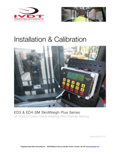
 Installation & Calibration
12 Pages
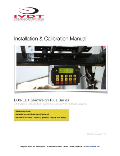
 ED3 SkidWeigh Plus Series
2 Pages
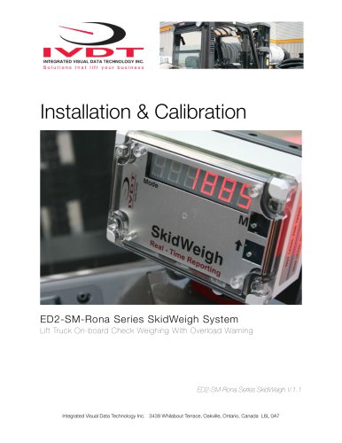
 SkidWeigh ED2
2 Pages
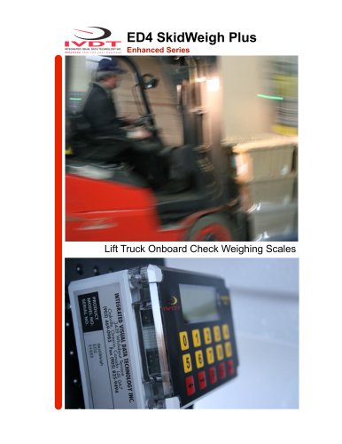
 ED4 SkidWeigh Plus Series
2 Pages
 ED4 SkidWeigh
10 Pages
 ED4 SkidWeigh
14 Pages
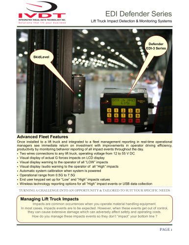
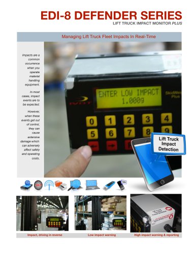
 Forklift Impacts detection
14 Pages
 ED3
ED314 Pages
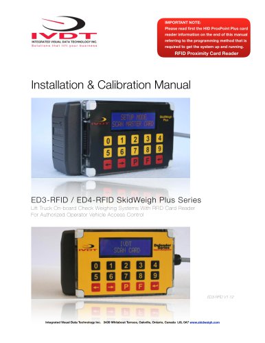 SkidWeigh ED3
23 Pages
 SkidWeigh Forklift Scale
10 Pages
 ED2-EP SkidWeigh
2 Pages
 Usage SkidWeigh
2 Pages
 ED3- SkidWeigh Plus-Print
9 Pages
 ED2-SkidWeigh
2 Pages
 SkidWeigh printers
4 Pages
 SP-1000 Series
11 Pages


- Measuring machine
- Waterproof scale
- Balance with separate indicator
- Access control system
- IP67 scale
- Management system
- Visual measurement system
- RFID access control system
- Impact monitoring system
- Communication controller
- Forklift truck scale
- Overload indicator
- Hydraulic scale
- Dimensional inspection system
- Digital overload indicator
- Forklift truck management system
- Forklift truck monitoring system
- Data communication controller