

ED3

ED3
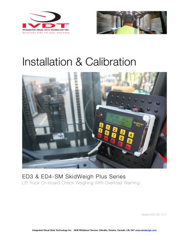
This section outlines the steps for installing, calibrating, testing, and using the ED4-PC SkidWeigh Plus V1.12 Series. It highlights the importance of following the ADMINISTRATION MENU guide for efficient setup and calibration. For further assistance, customer support is available.
During installation, disconnect the vehicle battery. Securely mount components and route cables to avoid interference with vehicle controls. Installation should be conducted by qualified technicians. Use soldering or crimp connectors for wire connections, ensuring they are mechanically sound and insulated. The system connects directly to the vehicle's ignition switch (12 to 55 VDC) and does not have an on-off switch.
The system complies with CE directive 89/336 (EMC) and standards EN 61000-6-2 and EN 61326-1 for interference stability and emission.
The system includes a digital indicator with an impact module, a hydraulic pressure transducer, and an installation manual. The digital indicator displays the software version upon power-up.
The system uses a hydraulic pressure transducer in the vehicle's lifting circuit to initiate a weighing cycle when a load is lifted. The pressure increase is converted into a load weight reading. The impact module self-calibrates upon power-up.
Install the transducer in the hydraulic line between the lift control valve and lift cylinder. Ensure the hydraulic circuit is pressure-free before installation. Use thread seal for a tight fit.
Mount the indicator vertically using the provided bracket. Ensure it is visible and within reach of the operator, without obstructing their view.
The system operates from 12 to 55 V DC. Specific wire connections are detailed for both the digital indicator and pressure transducer. The system includes internal short circuit protection.
After connecting power and the transducer, perform a quick test by turning on the ignition. The display should activate and show a load weight when the forks are lifted.
Access the menu by pressing F9 and entering a password. Set the date/time manually or automatically via a wireless RF platform. Configure the vehicle ID with a maximum of 3 digits (5 digits with RFID).
Catalog excerpts

Mounting Location for Digital Indicator with Optional Impact Detection Installation & Calibration Manual ED4-PC SkidWeigh Plus Series Lift Truck On-board Check Weighing & Parts Count Integrated Visual Data Technology Inc. 3439 Whilabout Terrace, Oakville, Ontario, Canada L6L 0A7 www.skidweigh.com
Open the catalog to page 1
General Installation Guide This ED4-PC SkidWeigh Plus V1.12 Series installation & calibration guide describes how to install, calibrate, test and use your on-board check weighing unit. Following the instructions in the ADMINISTRATION MENU guide will enable you to get the system set up and weighing calibration function operating quickly. In the event that you require additional assistance, please contact customer support via e-mail at [email protected] , visit www.skidweigh.com or contact us at the address or contact number below: Integrated Visual Data Technology Inc. 3439 Whilabout Terrace,...
Open the catalog to page 2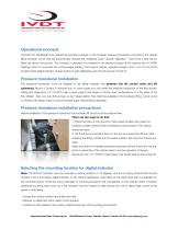
Operational principal The ED4-PC SkidWeigh Plus operational principal is based on the hydraulic pressure transducer mounted in the vehicle lifting hydraulic circuit that will automatically activate the “weighing cycle / specific algorithm ” every time a skid load is lifted just above the ground. The increase in pressure is converted in an electronic signal at the sample rate of 16000 readings which is converted into a load weight reading. The impact module operating range is from .5 to 16 G’s and is located inside digital indicator. Impact system is self calibrating each time the power turned...
Open the catalog to page 3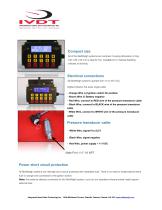
INTEGRATED VISUAL DATA TECHNOLOGY INC. Solutions that lift your business Compact size All of the SkidWeigh systems are compact, housing dimension of only 120 x 80 x 55 mm is ideal for the installations to material handling Electrical connections All SkidWeigh systems operate from 12 to 55 V DC. Digital indicator five wires single cable - Orange Wire (+) Ignition switch On position - Brown Wire (-) Battery negative - Red Wire, connect to RED wire of the pressure transducer cable - Black Wire, connect to BLACK wire of the pressure transducer - White Wire, connect to WHITE wire of the pressure transducer...
Open the catalog to page 4
“Quick test to determine if electrical connections are done right” Note 1: SkidWeigh weighing calibration function is not done yet at this stage. This procedure is only to test if electrical connections of the system installation into the vehicle is done properly! After you have connected electrical power and pressure transducer cable you can “quickly” check the system operation. - Turn On ignition switch - Digital LCD display will be activated, showing software version and serial number - Digital LCD display will show current date and time - When the LCD display is showing time /data lower the...
Open the catalog to page 5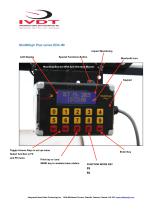
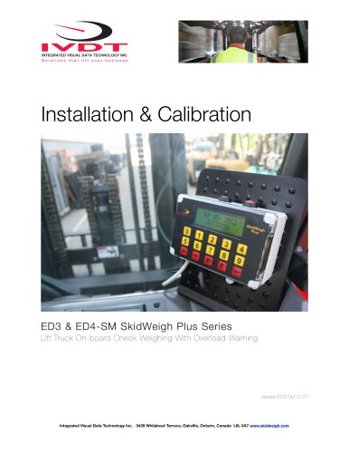
SkidWeigh Plus series ED3-IM Impact Monitoring LCD Display Special Functions Button Bluetooth Icon Mounting Bracket With Anti Vibration Mounts Toggle Arrows Keys in set up menu Select function in F0 and F9 menu Print key or /and SEND key to wireless base station Integrated Visual Data Technology Inc. 3439 Whilabout Terrace, Oakville, Ontario, Canada L6L 0A7 www.skidweigh.com
Open the catalog to page 6
Administrative Menu Instructions Time /Data Set Up To enter into the Administration Menu, press F9 and input password _____________ Use left and right arrow keys to scroll for function to be set and follow the LCD instructions. LCD Display MENU Password = ___ LCD Display Date / Time Set Up LCD Display SET CLOCK ENTER TO SELECT LCD Display SET CLOCK AUTO _ Use left and right ▶ arrow key (bottom left side of the keypad) to change from AUTO to MANUAL date/time set up. Note: AUTO set up refers to system utilizing a wireless RF platform with automatic date /time update from IVDT Base Station communication...
Open the catalog to page 7
Aug 28, 2010 12:20:23 Press “Enter key” ↵ to confirm the setting. The cursor will automatically move to the next item to be changed ( Month, Day, Year, Hours, Minutes, Seconds). On the last correction, seconds item press “Enter key” ↵ to confirm new date / time set up. Set vehicle ID - Maximum input number for vehicle ID is 3 digits. Note: For system used with RFID card reader maximum input number for vehicle ID is 5 digits. <> KEY to SCROLL F KEY TO EXIT LCD Display SET VEHICLE ID ENTER TO SELECT LCD Display ENTER VEHICLE ID 1_ LCD Display Integrated Visual Data Technology Inc. 3439 Whilabout...
Open the catalog to page 8
USB Port Protective Cover Saving recorded data to USB memory stick The SkidWeigh Plus system will allow you to download all recorded data onto a USB drive. Follow instructions shown on the LCD display This function is located in Supervisor Menu to protect the integrity of the information. <> KEY to SCROLL F KEY TO EXIT LCD Display SAVE TO USB ENTER TO SELECT LCD Display When the system has finished uploading the data to the USB memory stick the LCD display will prompt you to erase the SDRAM , all files contained on the SKidWeigh Plus ED3-IM . Once you have made your selection Y or N the system...
Open the catalog to page 9
Weighing scale function calibration The ED4-PC SkidWeigh Plus calibration is automatic and is done by lifting empty and loaded forks (or any other attachment such as paper clamp) just above the ground. MAKE SURE THAT YOU HAVE A KNOWN LOAD WEIGHT AND KEEP IT NEARBY TO COMPLETE THE CALIBRATION. For the best results use at least minimum calibration load test weight of 30 to 50% of maximum lifting capacity of the lift truck. Use customer floor scale or find a known skid load weight within the operational facility. Important: If you want the system to show load weight in pounds, use the known load weight...
Open the catalog to page 10
You must activate lift control valve and lift the empty forks just above the ground the same way that you would normally do when lifting loads. Do not slow down this lifting operational cycle, do not tilt the load, do not lift to different heights or move vehicle. Lift empty forks just above the ground . After few seconds the LCD display will show CALIBRATION 1 LOWER FORKS At this point you must lower the empty forks to the ground. The LCD display prompt you to input known calibration load weight. CALIBRATION 1 WEIGHT = ❏ Pick up a known load weigh and lower the loaded forks to the ground. (Our...
Open the catalog to page 11All Integrated Visual Data Technology Inc catalogs and technical brochures
 IM2-Defender Series
2 Pages
 Installation & Calibration
12 Pages
 ED3 SkidWeigh Plus Series
2 Pages
 SkidWeigh ED2
2 Pages
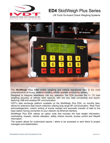 ED4 SkidWeigh Plus Series
2 Pages
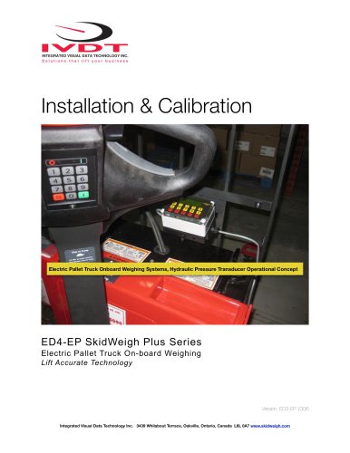 ED4 SkidWeigh
10 Pages
 ED4 SkidWeigh
14 Pages
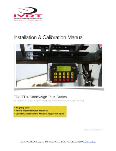 Forklift Impacts detection
14 Pages
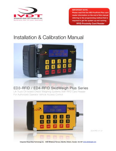 SkidWeigh ED3
23 Pages
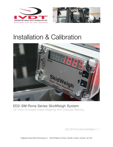 SkidWeigh Forklift Scale
10 Pages
 SidWeigh OL Series
11 Pages
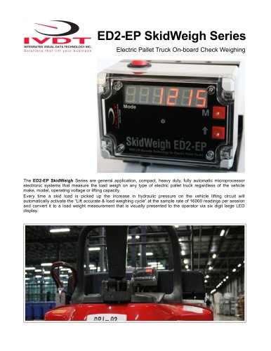 ED2-EP SkidWeigh
2 Pages
 Usage SkidWeigh
2 Pages
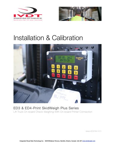 ED3- SkidWeigh Plus-Print
9 Pages
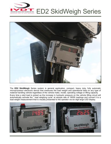 ED2-SkidWeigh
2 Pages
 SkidWeigh printers
4 Pages
 SP-1000 Series
11 Pages










- Measuring machine
- Waterproof scale
- Balance with separate indicator
- IP67 scale
- Access control system
- Management system
- Visual measurement system
- RFID access control system
- Communication controller
- Impact monitoring system
- Forklift truck scale
- Dimensioning system
- Hydraulic scale
- Overload indicator
- Forklift truck management system
- Digital overload indicator
- Forklift truck monitoring system
- Data communication controller