
- Catalogs
- Integrated Hydraulics
- Directional Controls

Directional Controls

Directional Controls
This document outlines the specifications for Eaton's Integrated Hydraulics threaded cartridge non-solenoid directional control valves. It serves as a guide for selecting Vickers cartridge valves or designing systems with these components. Certified drawings are recommended for critical measurements, and specifications may change without notice.
Directional control valves are designed for applications up to 350 bar (5000 psi) and 265 L/min (70 USgpm). Two pressure ratings are provided: typical application pressure and fatigue pressure, indicating the maximum recommended operating pressure and the pressure for infinite life free from metal fatigue, respectively.
- Fatigue tested for one million cycles at 132% or ten million cycles at 115% of rated pressure.
- Hardened steel parts for long life and low leakage.
- Compact design with zinc dichromate plating for corrosion resistance.
- Gold anodized aluminum manifolds and lockable settings.
- Available with aluminum knob and cap options.
The document includes a comprehensive list of models, cavities, flow ratings, pressures, and corresponding pages. Models include manual rotary valves, manual lever valves, manual push valves, and pilot to shift valves, among others.
Details on installation, including torque specifications for aluminum housings and dimensions, are provided. Diagrams for locating pin installations and alternative adjusters for light-duty aluminum housings are included.
Performance data is typical with fluid at 21.8 cSt (105 SUS) and 49°C (120°F). The document specifies typical application pressure, cartridge fatigue pressure, rated flow, temperature range, and internal leakage. It also lists manual operator options and compatible fluids.
A warning is included for pressures over 210 bar (3000 psi), recommending the use of steel housing. The document emphasizes the importance of proper filtration and cleanliness code adherence.
This document provides technical specifications and operational details for various models of manual rotary valves, specifically the MRV13-10, MRV13-12, MRV3-16, and MRV4-10. These valves are used for directional control in hydraulic systems and can function as diverters or dump valves.
- MRV13-10: 23 L/min (6 USgpm), 350 bar (5000 psi). Available in 2 or 3 position models with various manual operators including levers and knobs.
- MRV13-12: 46 L/min (12 USgpm), 350 bar (5000 psi). Similar operational features as MRV13-10.
- MRV3-16: 64 L/min (17 USgpm), 210 bar (3000 psi). Offers 2 or 3 position models with different manual operators.
- MRV4-10: 11 L/min (3 USgpm), 210 bar (3000 psi). A 4-way valve with 2 or 3 position options.
These valves direct flow between specified ports, blocking others depending on the position. The operator can be turned 90° to change the flow direction, with all ports blocked during cross-over transitions.
All models feature hardened, ground, and honed working parts to minimize leakage and extend lifespan. They are compatible with various hydraulic fluids and require specific cleanliness codes for filtration.
Valves are available with aluminum or steel housings, with specific torque requirements for installation. Aluminum housings are suitable for pressures up to 210 bar, while steel is required for higher pressures.
Ensure the correct housing material is used for the operating pressure to prevent failure. Certified drawings should be requested where measurements are critical.
This document provides detailed specifications and operational guidelines for EATON's manual rotary valves, specifically the MRV4 and MRV14 series. These valves are designed for high-pressure applications and are available in various sizes and configurations to suit different operational needs.
- Flow Rate: The MRV4 series supports a flow rate of 11 L/min (3 USgpm) at 210 bar (3000 psi), while the MRV14 series supports up to 45 L/min (12 USgpm) at 350 bar (5000 psi).
- Pressure Ratings: Typical application pressure is 350 bar (5000 psi) for MRV14 and 210 bar (3000 psi) for MRV4. Both series have a cartridge fatigue pressure rated for infinite life at these pressures.
- Temperature Range: Operational temperature ranges from -40°C to 120°C (-40°F to 248°F).
- Seal Materials: Options include Buna-N and Viton® seals.
- Manual Operators: Available in lever (2 or 3-position detent), ball (2 or 3-position detent), and knob (2-position, no detent) configurations.
- Function: MRV4 and MRV14 indicate manual rotary valves with 4-way functionality.
- Size: Available in sizes 10, 12, and 16.
- Port Size and Housing: Various port sizes are available, including BSPP and SAE standards, with options for aluminum or steel housings.
- Special Features: Typically none, unless specified.
These valves are designed for directing flow between ports in hydraulic systems. In the center condition, certain ports are open while others are closed, depending on the model. The operator can turn the valve 90° to change the flow direction between ports.
- Torque Specifications: Torque requirements vary based on housing material, with specific values provided for aluminum and steel housings.
- Filtration and Fluids: Compatible with general-purpose hydraulic fluids, maintaining a cleanliness code of 18/16/13.
- Weight: Cartridge weights vary by model, with detailed specifications provided.
Aluminum housings are suitable for pressures up to 210 bar, while steel housings are recommended for higher pressures. Certified drawings should be requested for critical measurements, and specifications are subject to change without notice.
The document provides detailed specifications and operational guidelines for various models of manual rotary and lever-operated directional control valves manufactured by Eaton. These valves are designed for high-pressure hydraulic systems and are used to control the direction of fluid flow.
- MRV15-16: A high-pressure 4-way, 2 or 3-position manual semi-rotary directional control valve with a flow rate of 45 L/min (12 USgpm) and a working pressure of 350 bar (5000 psi). It features hardened, ground, and honed working parts to limit leakage and prolong life.
- MRV6-10: A 4-way, 2 or 3-position manual semi-rotary directional control valve with a flow rate of 11 L/min (3 USgpm) and a working pressure of 210 bar (3000 psi). It is designed with various levers and knobs available with and without detent.
- MRV6-16: Similar to the MRV6-10 but with a higher working pressure of 350 bar (5000 psi).
- MRV7-10: A 4-way, 2 or 3-position manual semi-rotary directional control valve with all ports open to each other in the center condition.
- MLV9-12-A/B: Lever-operated 4-way, 3-position direct-acting spool type directional valves with a flow rate of 60 L/min (15.9 USgpm) and a working pressure of 210 bar (3000 psi).
The valves are compatible with general-purpose hydraulic fluids such as MIL-H-5606, SAE 10, and SAE 20. Standard housing materials include aluminum and steel, with specific torque requirements for cartridge installation.
The valves feature hardened, ground, and honed working parts to limit leakage and prolong life. They are available with various manual operators, including levers and balls with 3-position detents.
The document provides detailed installation drawings and torque specifications for different housing materials. It also includes information on seal kits and filtration requirements, emphasizing the importance of maintaining cleanliness codes 18/16/13.
Aluminum housings are suitable for pressures up to 210 bar (3000 psi), while steel housings are required for pressures above this threshold. The document advises requesting certified drawings where measurements are critical and reserves the right to change specifications without notice.
The document provides detailed technical specifications and operational guidelines for various types of manual lever and pull valves, specifically focusing on directional and check valves used in hydraulic systems. These valves are designed for ease of installation, durability, and efficient flow management.
- MLV9-12-E: A lever-operated, 4-way, 3-position spool type directional valve. It features a spring-centered design with all ports closed in the center position. Flow is directed between ports in different operational positions. Key features include hardened parts for reduced leakage, compact design, and adjustable handle position. It operates at a maximum flow of 60 L/min and a pressure of 210 bar.
- MLV9-12-F: Similar to the MLV9-12-E, but with a different center position configuration where ports 2 and 4 are open to the tank, and port 3 is blocked. It shares the same specifications and features as the MLV9-12-E.
- 3CP2 Series: Manually operated check valves that allow regulated flow when the hand knob is depressed. They are used in applications like lowering booms in power failures. The valve features machined seats and precision ground balls for excellent flow characteristics. It operates at a maximum pressure of 210 bar and flow rates depending on the orifice size.
- MPV1-10: A manually operated, normally closed poppet valve that opens when pulled. It is used as an emergency lower valve, allowing flow from port 1 to port 2 when the spring bias is overcome. It features hardened poppet and seat for low internal leakage and operates at a maximum flow of 45 L/min.
- MPV3-10: Similar to the MPV1-10 but includes a detent feature for maintaining the open position. It allows free flow in both directions when actuated.
- All valves are designed to operate with general-purpose hydraulic fluids and have a temperature range of -40° to 120°C.
- Standard housing materials are aluminum, and the valves are tested for endurance up to 1 million cycles at full rated flow and pressure.
- Filtration requirements are specified with a cleanliness code of 18/16/13.
The document includes performance graphs showing pressure drop against flow rates for each valve type, indicating efficient operation within specified parameters.
This document provides technical specifications and operational details for various models of EATON Screw-In Cartridge Valves, specifically focusing on manual push and twist directional control valves. These valves are designed for isolating systems until flow is required, with applications in hydraulic systems.
- MSV1-12: Rated flow of 41.8 L/min (11 USgpm) at 210 bar (3000 psi). Internal leakage is 350 cc/min. Temperature range is -40° to 120°C. Suitable for general-purpose hydraulic fluids.
- MSV11-10: Rated flow of 23 L/min (6 USgpm) at 350 bar (5000 psi). Internal leakage is 350 cc/min at 210 bar. Temperature range is -40° to 120°C. Compatible with aluminum and steel housings.
- MSV11-12: Rated flow of 30 L/min (8 USgpm) at 350 bar (5000 psi). Internal leakage is 350 cc/min at 350 bar. Temperature range is -40° to 120°C.
- MSV2-12: Rated flow of 38 L/min (10 USgpm) at 210 bar (3000 psi). Internal leakage is 350 cc/min. Temperature range is -40° to 120°C.
- MSV12-12: Rated flow of 38 L/min (10 USgpm) at 350 bar (5000 psi). Internal leakage is 350 cc/min at 210 bar. Temperature range is -40° to 120°C.
The valves operate in two positions: normal and actuated. In the normal position, flow is allowed from port 1 to port 2, while port 3 is blocked. In the actuated position, flow is allowed from port 3 to port 1, while port 2 is blocked.
The valves feature hardened, ground, and honed sleeves and spools for low internal leakage. A detent mechanism allows the valve to be fixed in position.
Torque specifications vary based on housing material. For aluminum housings, torque is 47-54 Nm (35-40 ft lbs), while for steel housings, it is 68-75 Nm (50-55 ft lbs).
Aluminum housings are suitable for pressures up to 210 bar (3000 psi). For pressures above this, steel housings must be used.
Each valve model has a specific code that denotes its function, size, seal material, actuation option, port size, and any special features.
The document provides detailed specifications and operational descriptions for various models of manual push valves, specifically the MSV series. These valves are designed for directional control in hydraulic systems, offering different configurations such as normally open or closed positions, and varying pressure ratings.
Each valve model is characterized by its flow rate, pressure rating, and operational temperature range. For instance, the MSV5-12 model supports a flow rate of 41.8 L/min at 210 bar, while the MSV15-12 model operates at 350 bar. The valves are compatible with general-purpose hydraulic fluids and require specific cleanliness codes for filtration.
The valves operate on a push and twist mechanism, allowing for two positions: normal and actuated. In the normal position, certain ports are blocked, while in the actuated position, flow is redirected between different ports. This mechanism is ideal for isolating systems or actuators until flow is required.
The valves feature hardened, ground, and honed sleeves and spools to minimize internal leakage. They also include a detent mechanism to fix the valve in position. The materials used for housing vary between aluminum and steel, depending on the pressure requirements.
Each valve model has a specific code that denotes its function, size, seal material, actuation option, port size, and any special features. For example, the MSV3-12 model is a 4-way, 2-position valve with options for different seal materials and actuation types.
The document provides detailed installation drawings and torque specifications for mounting the valves. Dimensions are given in both metric and imperial units, ensuring compatibility with various system requirements.
The document advises using steel housings for pressures above 210 bar and provides torque specifications for secure installation. It also emphasizes the importance of requesting certified drawings for critical measurements.
This document provides detailed specifications and operational guidelines for various models of EATON manual push valves, specifically designed for hydraulic systems. These valves are characterized by their push and twist actuation mechanism, offering directional control in hydraulic circuits.
- Working Pressure: Up to 350 bar (5000 psi) for most models, with some limited to 210 bar (3000 psi).
- Rated Flow: Ranges from 20 L/min (5.3 USgpm) to 53.2 L/min (14 USgpm) depending on the model.
- Temperature Range: -40°C to 120°C (-40°F to 248°F).
- Materials: Standard housing materials include aluminum and steel, with specific torque requirements for each.
- Seal Options: Available in Buna-N and Viton®.
- Filtration: Cleanliness code 18/16/13.
- MSV14-12: A 4-way, 2-position manual push valve with options for emergency stop actuation and detent mechanisms.
- MSV6-12: Normally closed valve ideal for isolating actuators, with a similar actuation mechanism.
- MSV16-12: High-pressure valve for isolating actuators, featuring a hardened sleeve and spool for low internal leakage.
- MSV17-10: Designed for reversing actuator direction, with a lower flow rate of 20 L/min.
- MSV7-12: Similar to MSV17-10 but with a higher flow rate of 45 L/min.
- Torque specifications vary based on housing material, with aluminum housings requiring 81-95 Nm and steel housings 102-115 Nm.
- Aluminum housings are suitable for pressures up to 210 bar, while steel is required for higher pressures.
- Ensure certified drawings are requested where measurements are critical.
- Specifications are subject to change without notice, emphasizing the need for up-to-date documentation.
This document provides technical specifications and operational details for various Eaton screw-in cartridge valves, including manual push valves, pilot to shift valves, and brake sequence valves. These valves are designed for hydraulic systems and are characterized by their high-pressure capabilities and low internal leakage.
- Working Pressure: Up to 350 bar (5000 psi).
- Temperature Range: -40°C to 120°C (-40°F to 248°F).
- Flow Rates: Varying from 10 L/min (2.5 USgpm) to 114 L/min (30 USgpm) depending on the valve type.
- Materials: Standard housing materials include aluminum and steel, with all working parts made of hardened and ground steel.
- Seal Options: Available in Buna-N and Viton®.
- Manual Push Valve (MSV17-12): A 4-way, 2-position valve with a 'push and twist' actuation option, suitable for applications requiring manual control.
- Pilot to Shift Valve (PTS7-10, PTS17-10, PTS17-12): 2-way, 2-position valves that operate by pilot pressure to isolate functions. They feature hardened, ground, and honed sleeves and spools for low internal leakage.
- Brake Sequence Valve (1SB10): Designed to control brake circuits by maintaining a bias pressure before switching, ensuring controlled application of brakes.
- Internal Leakage: Ranges from 50 ml/min to 350 cc/min depending on the valve and pressure conditions.
- Filtration Requirements: Cleanliness code 18/16/13, with a nominal viscosity range of 5 to 500 cSt.
- Torque Specifications: Vary based on housing material, with specific torque values provided for aluminum and steel housings.
- Warnings: Aluminum housings are limited to pressures up to 210 bar (3000 psi), while steel housings are required for higher pressures.
The document includes pressure drop curves and sectional views for each valve type, illustrating flow characteristics and operational behavior under specified conditions.
This document provides technical specifications and operational details for various EATON screw-in cartridge valves, including brake release shuttle valves and pilot to shift valves. It includes descriptions, operations, features, ratings, specifications, and model codes for each valve type.
- Description: This valve supplies oil to the outlet from the inlet when a preset pressure is reached, ideal for braking systems.
- Operation: Allows flow from inlet to outlet when pressure exceeds set level; closes tank line when pressure is removed.
- Specifications: Max working pressure of 350 bar, rated flow of 30 L/min, temperature range -30° to 90°C, and internal leakage of 50 ml/min.
- Materials: Hardened and ground steel parts, zinc-plated external surfaces.
- Description: Interrupts a pressure line when a predetermined pilot pressure is reached, used in pilot or small flow systems.
- Operation: Spool moves to open or close the line between inlet and outlet based on pilot pressure.
- Specifications: Max working pressure of 420 bar, rated flow of 80 L/min, temperature range -30° to 90°C, and internal leakage of 90 ml/min.
- Materials: Hardened and ground steel parts, zinc-plated external surfaces.
- Description: A 3-way 2-position valve for selecting a function when pilot pressure is applied or removed.
- Operation: Allows flow between ports 2 and 3 while blocking port 4 until sufficient pressure is applied to port 1.
- Specifications: Max working pressure of 210 bar, rated flow of 30 L/min, temperature range -40° to 120°C, and internal leakage of 164 cc/min.
- Materials: Aluminum and steel housings, hardened and ground steel parts.
- Description: A high-pressure pilot operated valve for selecting a function when pilot pressure is applied or removed.
- Operation: Similar to PTS1-10, with flow directed between ports 3 and 4 when pressure is applied to port 1.
- Specifications: Max working pressure of 350 bar, rated flow of 76 L/min, temperature range -40° to 120°C, and internal leakage of 210 cc/min.
- Materials: Aluminum and steel housings, hardened and ground steel parts.
- All valves feature cartridge designs for easy servicing.
- Standard housing materials include aluminum and steel, with specific pressure ratings for each.
- Filtration requirements are specified as BS5540/4 Class 18/13 or better.
- Viton® is a registered trademark of E.I. DuPont, used for seal kits.
The document describes a series of high-pressure pilot-operated directional control valves, specifically 3-way 2-position valves, designed for selecting functions when pilot pressure is applied or removed. These valves are suitable for applications requiring high pressure and precise control.
The valves allow flow between specific ports while blocking others until sufficient pressure is applied to overcome the spring bias. During the transition between positions, all ports are blocked, and the spring chamber is vented to a designated port.
The valves operate at a typical application pressure of 350 bar (5000 psi) with a rated flow of up to 132 L/min (35 USgpm). Internal leakage is minimal, and the valves are designed for a wide temperature range from -40°C to 120°C (-40°F to 248°F).
The valves feature hardened, ground, and honed sleeves and spools to ensure low internal leakage and durability. They are available with different seal materials, including Buna-N and Viton®, and can be housed in aluminum or steel, depending on the pressure requirements.
The document includes pressure drop curves for various flow rates, indicating the efficiency and performance of the valves under different conditions.
The document provides detailed model codes for different valve configurations, including size, seal material, port size, pilot pressure, and special features. It also includes torque specifications for installation in different housing materials.
The document warns that aluminum housings are suitable for pressures up to 210 bar (3000 psi), while steel housings are required for higher pressures.
Detailed installation drawings and dimensions are provided for both aluminum and steel housings, ensuring proper installation and operation of the valves.
This document provides detailed specifications and operational descriptions for various models of pilot-operated directional control valves, specifically the PTS5-16, PTS15-16, PTS6-16, and PTS16-16. These valves are designed for hydraulic systems and are used to control the direction of fluid flow based on pilot pressure.
- Performance Data: The valves operate with a typical fluid viscosity of 21.8 cST at 49°C. They have a rated flow of 132 L/min (35 USgpm) and can handle pressures up to 350 bar (5000 psi) depending on the model.
- Temperature Range: The operational temperature range is from -40°C to 120°C.
- Internal Leakage: Maximum internal leakage is specified at 164 cc/min at 210 bar for some models and 210 cc/min at 350 bar for others.
- Materials: Standard housing materials include aluminum and steel, with specific models requiring steel for higher pressure applications.
- Seal Kits: Available in Buna-N and Viton® materials.
- The valves are 3-way, 2-position, pilot-operated, and are used to select functions when pilot pressure is applied or removed.
- Flow is directed between specific ports based on the applied pressure, with all ports open during the cross-over transition.
- The spring chamber is vented to atmosphere or a specific port depending on the model.
- Hardened, ground, and honed sleeve and spool for low internal leakage.
- Pressure drop curves and sectional views are provided for performance analysis.
- Torque specifications for installation vary based on housing material, with specific values provided for aluminum and steel housings.
- Detailed dimensional drawings are included for accurate installation.
- Aluminum housings are suitable for pressures up to 210 bar, while steel housings are required for pressures above this threshold.
The document provides detailed specifications and operational guidelines for EATON's Screw-In Cartridge Valves, specifically focusing on the PTS9 series of pilot-operated directional control valves and the 1HSH20 hot oil shuttle valve.
- Function: These are 3-way, 2-position valves used for directing flow based on pilot pressure.
- Specifications: Available in various sizes (C-8-5S, C-10-5S, C-12-5S, C-16-5S, C-20-5S) with rated flows ranging from 19 L/min to 230 L/min and a maximum pressure of 280 bar (4000 psi).
- Materials: Seal materials include Buna-N and Viton®, with housing options in aluminum or steel depending on pressure requirements.
- Operation: Flow is directed between ports 3 and 4 or 3 and 2 based on pilot pressure, with all ports open during transition.
- Features: Hardened, ground, and honed components for low internal leakage.
- Function: Designed for hot oil exhaust in closed-loop hydrostatic systems, allowing excess oil to be purged through a back pressure relief valve.
- Specifications: Rated for 20 L/min flow at 350 bar (5000 psi) with a temperature range of -30° to 90°C.
- Operation: The valve opens the low-pressure line to the tank when pressure rises in either inlet line, maintaining hot oil exhaust.
- Features: Compact design with high pressure rating and minimal cross-port leakage.
- All valves are designed to operate with general-purpose hydraulic fluids and require specific cleanliness codes for filtration.
- Aluminum housings are suitable for pressures up to 210 bar, while steel is required for higher pressures.
- Certified drawings should be requested for critical measurements, and specifications are subject to change without notice.
The document provides detailed specifications and operational guidelines for various types of directional and shuttle valves used in hydraulic systems. These valves are designed to manage fluid flow and pressure in industrial applications, ensuring efficient operation and longevity of hydraulic systems.
- Directional Valve (1HSH Series): Available in cartridge only or with body, with a flow rate of 20 L/min and pressure capacity of 350 bar. Port sizes vary, and seal options include Nitrile and Viton for different fluid applications.
- Shuttle Valve (DSV4 Series): Includes models like DSV4-10, DSV4-12, and DSV4-16, with flow rates ranging from 26 L/min to 190 L/min and pressure capacity of 350 bar. These valves are available in open or closed center spool configurations.
- Hot Oil Shuttle Valve (1HSH701): Designed for hot oil exhaust in closed loop systems, with a flow rate of 80 L/min and pressure capacity of 420 bar.
- Directional Valves: These valves control the direction of fluid flow in hydraulic systems. The operation involves overcoming spring bias to direct flow between specified ports.
- Shuttle Valves: Used in transmission applications, these valves direct flow based on pressure changes at specific ports, available in both open and closed center configurations.
- Hot Oil Shuttle Valves: These valves manage the exhaust of hot oil in hydrostatic systems, ensuring efficient system purging and pressure management.
- Valves are constructed with hardened, ground, and honed parts to minimize leakage and extend service life.
- Standard housing materials include aluminum for pressures up to 210 bar and steel for higher pressures.
- Seal kits are available in Buna-N and Viton, catering to different temperature and fluid compatibility requirements.
- Typical application pressures are up to 350 bar, with internal leakage specifications provided for each valve type.
- Temperature ranges for operation are specified, ensuring compatibility with various industrial environments.
- Filtration requirements and cleanliness codes are outlined to maintain optimal valve performance.
- Installation drawings and torque specifications are provided for proper valve fitting.
- Regular maintenance and adherence to specified operating conditions are recommended to ensure valve longevity and performance.
This document provides technical specifications and operational details for Eaton's screw-in cartridge valves, specifically the PTS6-10 and PTS16-12 pilot to shift valves. These valves are remotely pilot-operated directional control valves designed for high-pressure applications.
- PTS6-10 Valve: Rated flow of 23 L/min (6 USgpm) and a working pressure of 210 bar (3000 psi). It features a hardened, ground, and honed sleeve and spool for low internal leakage.
- PTS16-12 Valve: Rated flow of 76 L/min (20 USgpm) and a working pressure of 350 bar (5000 psi). Similar construction features as the PTS6-10 for durability and performance.
Both valves allow flow between specific ports until sufficient pilot pressure is applied to shift the valve position. During the transition, all ports are blocked to prevent leakage.
The valves are available with aluminum or steel housings, with specific torque requirements for installation. Aluminum housings are suitable for pressures up to 210 bar, while steel housings are required for higher pressures.
The document includes pressure drop curves and flow rates for different oil viscosities and temperatures, providing insights into the valve's efficiency under various conditions.
Detailed dimensions and installation instructions are provided, emphasizing the importance of using certified drawings for critical measurements. The document also outlines the availability of factory service and repair programs through Eaton's distributor network.
Users are cautioned about the pressure limitations of aluminum housings and are advised to use steel housings for higher pressure applications. Proper filtration and cleanliness codes are recommended to ensure optimal valve performance.
Catalog excerpts
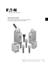
Manual and pilot operated directional control valves for applications up to 350 bar (5000 psi) and 265 L/min (70 USgpm) Where measurements are critical request certified drawings. We reserve the right to change specifications without notice. EATON Screw-In Cartridge Valves E-VLSC-MC001-E1 September 2013
Open the catalog to page 1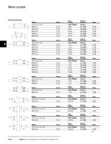
Valve Locator Manual rotary valve Typical Pressure Flow Rating L/min (USgpm) Flow Rating Typical Pressure L/min (USgpm) Flow Rating Typical Pressure Manual rotary valve L/min (USgpm) Flow Rating Typical Pressure L/min (USgpm) Flow Rating Typical Pressure L/min (USgpm) Manual rotary valve 1 3 Manual rotary valve 1 2 Manual rotary valve Flow Rating Typical Pressure L/min (USgpm) Manual lever valve, spool Flow Rating Typical Pressure L/min (USgpm) Flow Rating Typical Pressure L/min (USgpm) Manual lever valve, spool 3 Manual lever valve, spool Flow Rating Typical Pressure L/min (USgpm) Manual lever...
Open the catalog to page 2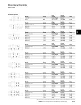
Directional Controls Valve locator Flow Rating Typical Pressure L/min (USgpm) Flow Rating Typical Pressure L/min (USgpm) Flow Rating Typical Pressure L/min (USgpm) Manual pull valve, NC Manual push valve Flow Rating Typical Pressure L/min (USgpm) Flow Rating Typical Pressure L/min (USgpm) Manual push valve Manual push valve 3 Flow Rating Typical Pressure L/min (USgpm) Flow Rating Typical Pressure L/min (USgpm) Manual push valve Manual push valve Flow Rating Typical Pressure L/min (USgpm) Flow Rating Typical Pressure L/min (USgpm) Manual push valve Manual push valve Where measurements are critical...
Open the catalog to page 3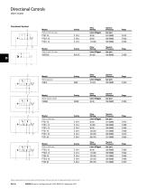
Directional Controls Valve locator Functional Symbol Model Pilot to shift 2/2 valve Flow Rating Typical Pressure L/min (USgpm) Flow Rating Typical Pressure L/min (USgpm) Pilot to shift 2/2 valve Flow Rating Typical Pressure L/min (USgpm) Brake sequence Flow Rating Typical Pressure L/min (USgpm) Brake release shuttle Flow Rating Typical Pressure L/min (USgpm) Pilot to shift valve Flow Rating Typical Pressure L/min (USgpm) Pilot to shift valve Where measurements are critical request certified drawings. We reserve the right to change specifications without notice. EATON Screw-In Cartridge Valves...
Open the catalog to page 4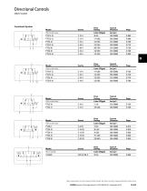
Directional Controls Valve locator Functional Symbol Model Pilot to shift valve Flow Rating Typical Pressure L/min (USgpm) Pilot to shift valve Flow Rating Typical Pressure L/min (USgpm) Flow Rating Typical Pressure L/min (USgpm) Pilot to shift valve Flow Rating Typical Pressure L/min (USgpm) Pilot to shift valve Flow Rating Typical Pressure L/min (USgpm) Where measurements are critical request certified drawings. We reserve the right to change specifications without notice. EATON Screw-In Cartridge Valves E-VLSC-MC001-E1 September 2013
Open the catalog to page 5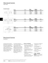
Directional Controls Valve locator Functional Symbol Model Flow Rating Typical Pressure L/min (USgpm) Flow Rating Typical Pressure L/min (USgpm) Flow Rating Typical Pressure L/min (USgpm) Pilot to shift valve Directional Controls Introduction This section gives the basic specifications for the complete line of Eaton's Integrated Hydraulics threaded cartridge non-solenoid directional control valves. Its purpose is to provide a quick, convenient reference tool when choosing Vickers cartridge valves or designing a system using these components. Two pressure ratings are shown for all products featured...
Open the catalog to page 6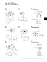
Alternative Adjusters For Light Duty Aluminum Housings Only Locating pin hole, four optional slots in detent plate This hole omitted from detent plate of MRV3-10(V)-D2/E2 Ø 3,45/3,50 (#29 or 0.136) drill x 4,8 (0.187) deep in mating housing Locating pin hole, four optional slots in detent plate Ø 3,45 3,50 (#29 or 0.136) drill x 4,8 (0.187) deep in mating housing Where measurements are critical request certified drawings. We reserve the right to change specifications without notice. EATON Screw-In Cartridge Valves E-VLSC-MC001-E1 September 2013
Open the catalog to page 7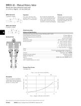
MRV3-10 - Manual Rotary Valve Manual semi-rotary directional control valve 23 L/min (6 USgpm) • 210 bar (3000 psi) By turning the operator 90°, flow will be directed between ports 1 and 2 and port 3 will be blocked. During cross-over transition, all ports are blocked. This valve will direct flow between ports 1 and 3 and block port 2 in one position. Hardened, ground and honed working parts to limit leakage and prolong life. Various levers and knobs available with and without detent. Performance Data Performance data is typical with fluid at 21,8 cSt (105 SUS) and 49°C (120°F) Typical application...
Open the catalog to page 8
MRV3-10 - Manual Rotary Valve Manual semi-rotary directional control valve 23 L/min (6 USgpm) • 210 bar (3000 psi) Model Code MRV3 - Manual rotary valve 4-way Port Size Port Size 00 - None (Only required if valve has special features, omitted if “00”.) Housing Number Aluminum Fatigue Rated O - No operator D - Level (3-position detent) D2 - Level (2-position detent) E - Ball (3-position detent) E2 - Ball (2-position detent) K - Knob (2-position, no detent) Manual Operator Blank - Buna-N VViton Seal Material Special Features SS - 316 stainless steel external components (only available for "0" and...
Open the catalog to page 9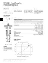
MRV13-10 - Manual Rotary Valve Manual semi-rotary directional control valve 23 L/min (6 USgpm) • 350 bar (5000 psi) Features By turning the operator 90°, flow will be directed between ports 1 and 2 and port 3 will be blocked. During cross-over transition, all ports are blocked. This valve will direct flow between ports 1 and 3 and block port 2 in one position. Hardened, ground and honed working parts to limit leakage and prolong life. Various levers and knobs available with and without detent. Working pressure 350 bar. Performance Data Performance data is typical with fluid at 21,8 cSt (105 SUS)...
Open the catalog to page 10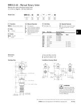
MRV13-10 - Manual Rotary Valve Manual semi-rotary directional control valve 23 L/min (6 USgpm) • 350 bar (5000 psi) Model Code MRV13 - Manual rotary valve Manual Operator - No operator - Lever (3-position detent) - Lever (2-position detent) - Ball (3-position detent) - Ball (2-position detent) - Knob (2-position, no detent) Blank - Buna-N V - Viton® Port Size Special Features 00 - Non (Only required if valve has special features, omitted if “00”) Port Size Housing Number 1/4” BSPP 3/8” BSPP SAE 6 SAE 8 1/4” BSPP 1/3” BSPP SAE 6 SAE 8 Torque cartridge in housing A - 47-54 Nm (35-40 ft. lbs) S...
Open the catalog to page 11All Integrated Hydraulics catalogs and technical brochures
 Industrial Valves
8 Pages
 Industrial Hose Master Catalog
366 Pages
 pct_292502
198 Pages
 pct_292303
124 Pages
 pct_292302
74 Pages
 pct_285346
170 Pages
 pct_292306
124 Pages
 Solenoid Valves Coil
2 Pages
 Needle Valves 2CN20
2 Pages
 Motion Control 1CE20
2 Pages
 Dual Relief Valves 1DDR35
2 Pages
 Shuttle Valves 1SH10
2 Pages
 Flow Dividers 2CFD50
2 Pages
 Check 3CP2
2 Pages
 Reducing Valves 1PD20
2 Pages
 Relief Valves 1AR60
2 Pages


- Cylinder
- Flap valve
- Double-acting cylinder
- Hydraulic cylinder
- Oil valve
- Hydraulic valve
- Hydraulic directional control valve
- Flow control valve
- Hydraulically-operated valve
- Electrically-operated hydraulic directional control valve
- Hydraulic check valve
- Tie-rod cylinder
- Proportional valve
- Cartridge check valve
- Solenoid-operated hydraulic directional control valve