


- Company
- Products
- Catalogs
- News & Trends
- Exhibitions
Spinal Fixtures ASTM F1717 - CP113023

Spinal Fixtures ASTM F1717 - CP113023
Spinal constructs are subjected to high in vivo loading, which can lead to catastrophic failure. Spinal injuries often result from rotation, dislocation, bending, and axial loading. Testing methods such as static and cyclic testing are used to evaluate the load and fatigue failure of spinal implants.
ASTM F1717-12 Standard
The ASTM F1717-12 standard provides guidelines for mechanical comparison of spinal implant assemblies through static compression bending, static tension bending, static torsional test, and fatigue testing. It also offers guidance on the use of ultra-high molecular weight polyethylene (UHMWPE) blocks.
Instron Spinal Fixture
The Instron spinal fixture is designed to meet ASTM F1717-12 requirements and is compatible with ElectroPuls Test Instruments, particularly the E3000 and E10000 models. It allows for bending compression, bending tensile, and torsional testing.
Principle of Operation
The fixture is easily assembled and mounted on ElectroPuls Test Instruments. It is compatible with a saline bath for in vivo testing and features a maximum load rating of 1 kN for tension/compression and 50 Nm for static torsion.
Features and Benefits
- Compatible with ElectroPuls E3000 and E10000 for static and dynamic testing.
- Saline bath for simulating in vivo testing.
- Patented stiffness-based tuning for waveform fidelity and repeatability.
- WaveMatrix™ Software for accurate testing across frequency ranges.
- Dynacell load cell compensates for load inertia errors.
Specifications
Upper Fixture Dimensions: 236 × 120 × 40 mm
Lower Fixture Dimensions: 130 × 120 × 40 mm
Maximum Static Force: ±1000 N
Maximum Torsional Force: ±50 Nm
Accessories include a 6-liter fluid bath and a longer saline bath tube.
Contact Information
Instron is a registered trademark of Illinois Tool Works Inc. For more information, visit www.instron.com or contact their worldwide headquarters in Norwood, MA, USA, or their European headquarters in High Wycombe, UK.
Catalog excerpts

Spinal Fixtures During normal patient activity, spinal constructs can be subjected to high in vivo loading that can result in catastrophic failure. Spinal injuries often occur due to rotation, dislocation, bending, and axial loading. Simple static testing is able to evaluate the load required to result in spinal fracture. Cyclic testing is also performed in order to evaluate the amount of cycles it takes for fatigue failure to occur. ASTM F1717-12 ‘Standard Test Methods for Spinal Implant Constructs in a Vertebrectomy Model’ provides a guidance for the mechanical comparison between past, present, and future spinal implant assemblies through four different test methods: static compression bending, static tension bending, static torsional test, and fatigue testing. As spine implants are manufactured and designed from different companies, the standard also offers a guidance on the ultra-high molecular weight polyethylene (UHMWPE) blocks, including their size and geometry. ASTM F1717-12 provides test methods that set guidelines for load types and offers a comparative evaluation of spinal implant assemblies, but it does not define the levels of performance. The Instron® spinal fixture is designed to meet ASTM F1717-12 requirements. In accordance to the standard, the UHMWPE blocks are attached to the spinal fixture. The design of the blocks can differ, according to the clinical application at the intended spinal location. The way that the blocks are connected to the fixture allow a degree of freedom when performing bending compression, bending tensile, and torsional testing. The spinal fixture is compatible with all ElectroPulsTM Test Instruments, but it is ideally used with the E3000 and E10000 models for customers performing torsional testing. Principle of Operation Instron’s spinal implant was designed to meet ASTM F1717-12 requirements, in regards to the tension and torsional sections of the standard. The fixture is easily assembled and mounted on the base of an ElectroPuls Test Instrument. Moreover, it is compatible with the saline bath (CP100543) for in vivo testing when fitted with a longer saline bath tube (CP111212). The fixture is attached on the saline bath and the load cell through clevis fixtures. Also, support straps fit between the clevis grips to maintain rigidity of fixture assembly during installation in the saline bath. The maximum load rating of the fixture is 1 kN tension/tension, 1 kN compression/compression, and 50 Nm static torsion. The spine fixture is designed to be used with an ElectroPuls E3000 and E10000 models. • The ElectroPuls E3000 and E10000, with the biaxial actuator, can perform both static and dynamic testing on a single machine, meeting the ASTM F1717-12 requirements • The saline bath can be easily mounted on the ElectroPuls for simulating in vivo testing • Instron’s patented stiffness based-tuning ensures waveform fidelity and repeatability • The ElectroPuls, when using WaveMatrix™ Software, is perfect for testing spinal constructs for exceptional response and accuracy across the frequency range • Instron’s patented Dynacell load cell compensates for load inertia errors providing accurate and reliable data www.instron.com Accessories for Materials Testing
Open the catalog to page 1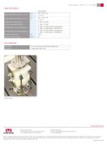
Spinal Fixtures | ASTM F1717 - CP113023 Specifications CP113023 Upper Fixture Dimensions (h × w × d) Lower Fixture Dimensions (h × w × d) E3000 Upper Base Interface E10000 Upper Base Interface 3 × M6 × 75 PCD 3 × M6 × 57 PCD (Ambient Temperature) 3 × M6 × 57 PCD (When in CP100543) 3 × M8 × 75 PCD (Ambient Temperature) 3 × M6 × 57 PCD (When in CP100543) E3000 Biaxial Lower Base Interface E10000 Biaxial Lower Base Interface Maximum Static Force Maximum Torsional Force 6 Liter Fluid Bath for Biomedical Applications Longer Saline Bath Tube Spinal Fixture www.instron.com Worldwide Headquarters 825...
Open the catalog to page 2All Instron catalogs and technical brochures
 CEAST 9000 Series
20 Pages
 MFi Series Melt Flow Testers
16 Pages
 Automated Testing Systems
20 Pages
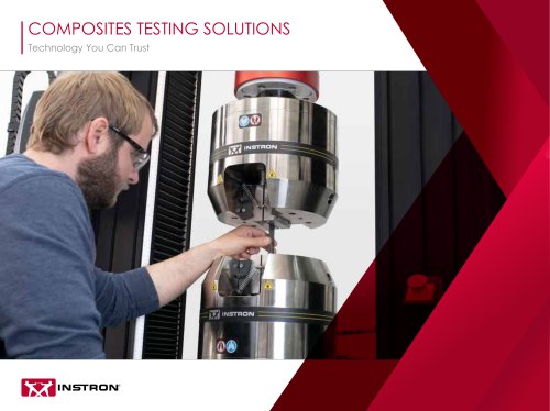 Composites Testing Solutions
20 Pages
 DX MODELS
3 Pages
 2580 Series Load Cells
3 Pages
 HDX Models
2 Pages
 DAMPER TEST SYSTEMS BI-7080
2 Pages
 HIGH STRAIN RATE VHS SYSTEM
4 Pages
 Automated XY Testing System
3 Pages
 CEAST 9400 Series
20 Pages
 COMPRESSION PLATENS
2 Pages
 LOW CYCLE FATIGUE
11 Pages
 ElectroPuls™
10 Pages
 Pneumatic Side-Action Grips
4 Pages
 HDT AND VICAT TESTING SYSTEMS
16 Pages
 AlignPRO™ Alignment System
2 Pages
 CEAST Melt Flow Series
20 Pages
 CEAST SmartRheo Series
16 Pages
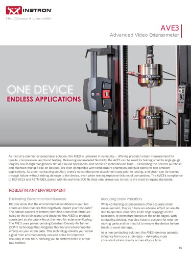
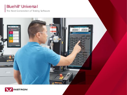

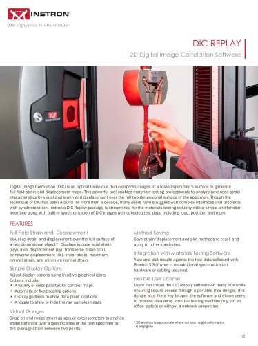


Archived catalogs
 CEAST HDT Vicat Series
9 Pages
- Valve
- Control valve
- Kiln
- Instron testing machine
- Chamber kiln
- Test cabinet
- Linear actuator
- Automation software solution
- Management software solution
- Positioning table
- Electric valve
- Analysis software solution
- Test stand
- Process software
- Instron tension/compression load cell
- Temperature test chamber
- Real-time software
- Instron Windows software