
- Catalogs
- INGUN Prüfmittelbau
- Test Probes


Test Probes

Test Probes
Grid Definition: The grid refers to the distance between test points on a PCB, measured in inches (Mil). Common grid sizes include 40 Mil (1.0 mm), 50 Mil (1.27 mm), 75 Mil (1.91 mm), and 100 Mil (2.54 mm).
Spring Force: A balance is needed between low and high spring force to ensure reliable contact without stressing the device under test (DUT).
Receptacle Types: Receptacles with collars or press-rings regulate installation height. Threaded test probes are used in challenging conditions to prevent loosening.
Test Probes: Various test probes are available for different applications, including standard, long stroke, wireless, short/robust, rotating, bead, and fine pitch probes. Each type is suited for specific grid sizes and conditions.
Standard stroke probes are reliable for ICT/FCT tests. Long stroke probes are used in dual-stage fixtures. Wireless receptacles eliminate the need for cables. Short/robust probes are compact for harsh conditions. INGUN E-TYPE® probes have higher preload for secure contact. Rotating probes penetrate insulating layers. Bead probes contact beads on PCBs. Fine pitch probes are for small test points.
- GKS-040: Features a working stroke of 4.3 mm and a maximum stroke of 6.35 mm. The current rating is 2 A, with a typical resistance of less than 20 mW. The plunger is made of steel or BeCu, and all components are gold-plated for enhanced conductivity.
- GKS-050: Offers a working stroke of 4.3 mm and a maximum stroke of 6.35 mm. It supports a current rating of 2-3 A. The materials used include BeCu or steel for the plunger, with gold plating on all parts.
- GKS-075: Designed for a working stroke of 4.3 mm and a maximum stroke of 6.35 mm, with a current rating of 3-4 A. The plunger and barrel are gold-plated, and the spring is available in steel or stainless steel.
- GKS-100: This probe supports a working stroke of 4.3 mm and a maximum stroke of 6.35 mm, with a current rating of 5-8 A. It features a BeCu or steel plunger, with gold plating on all components.
- Receptacles are designed with press-rings to adjust installation height, acting as a collar-stop or being pressed into the mounting hole.
- Mounting hole sizes are specified for different materials like CEM1 and FR4, ensuring compatibility and secure fitting.
- Examples are provided for ordering, detailing series, tip material, tip style, diameter, plating, spring force, and collar height.
- Operating temperature for standard components ranges from -40° to +80° C, with special designations allowing for higher temperatures.
- All specifications are subject to change without prior notification, emphasizing the need for verification before ordering.
Receptacles with a press-ring (designation “G”) are used to adjust the installation height. This can be achieved by assembling the collar lower in the mounting hole.
Materials include Steel and BeCu, with gold plating available. The tip diameter is specified in 1/100 mm. Spring force options range from 2.0 N to 5.0 N, and the operating temperature is from -40° to +80° C.
Working stroke is 4.4 mm with a maximum stroke of 6.35 mm. Current rating is between 6 - 8 A, with a typical resistance of less than 20 mW. Materials used include steel, nickel-silver, and bronze, all gold-plated.
These probes offer high contact security with increased spring pre-load, providing a larger contact area. They are available in grid sizes of 50, 75, and 100 Mil and are compatible with standard series GKS-050/075/100/422.
Recommended for secure contact on contaminated or plated surfaces. The rotating plunger pierces the surface, requiring adjusted maintenance due to increased particles.
Examples include series, tip material, tip style, diameter, plating, spring force, and collar height. Various configurations are available for different applications.
Specifications are subject to change. The document provides detailed mechanical data, spring forces, and compatible probe series for different models like E-050, E-075, E-100, and E-422.
- Test Probes: Various series such as GKS 038, GKS 061, GKS 080, GKS 081, GKS 069, GKS 079, and GKS 181 are covered, each with specific grid sizes, installation heights, and recommended strokes.
- Materials: Common materials include BeCu, brass, bronze, and steel, all gold-plated for enhanced conductivity and durability.
- Electrical Data: Current ratings typically range from 2 to 3 A, with resistance (Ri) values generally below 30 mW.
- Mechanical Data: Working strokes vary from 1.0 mm to 5.5 mm, with corresponding spring forces ranging from 0.7 N to 1.5 N.
- Mounting Hole Sizes: Specific diameters are provided for mounting with and without receptacles, depending on the material (CEM1, FR4).
- Ordering Information: Examples are given for ordering probes with specific tip materials, styles, diameters, and plating options.
- Installation Guidelines: Recommendations include minimal bending radii for pre-wired versions and collar height adjustments for installation flexibility.
- Operating Temperature: Standard operating range is from -40°C to +80°C.
- Metric Standards: The document highlights the robustness and stability of metric standard test probes, suitable for various applications including ICT/FCT.
- All specifications are subject to change without prior notification.
- Special designations and configurations are available for specific applications, such as bent barrel ends or continuous plungers for higher currents.
1. Receptacles and Mounting: The KS-112 series receptacles are designed for various installation heights, with options for different collar heights. The mounting hole sizes vary depending on the material (CEM1 or FR4) and whether a collar or press-ring is used. Materials include brass, nickel-silver, and bronze, all gold-plated.
2. Test Probes: The GKS series test probes are available in different models (112, 412, 422, 912) with varying grid sizes (≥ 2.54 mm or ≥ 100 Mil) and installation heights. Recommended strokes range from 4.0 mm to 8.0 mm, with maximum strokes slightly higher. Spring forces vary from 0.6 N to 5.0 N.
3. Electrical and Mechanical Data: The current rating for these probes is between 5 - 8 A, with a typical resistance (Ri) of less than 20 mW. The operating temperature ranges from -40°C to +80°C, with special versions extending from -100°C to +200°C.
4. Materials: Plungers are made from BeCu or steel, barrels from nickel-silver or brass, and springs from steel, all with various plating options including gold, rhodium, and nickel.
5. Ordering Information: The document provides detailed ordering examples for different configurations of receptacles and test probes, specifying series, tip material, tip style, diameter, plating, spring force, and collar height.
Key Recommendations and Notes:
- Use spacers to adjust installation heights, but note that they may reduce the holding force of test probes.
- For vacuum fixtures, use vacuum-sealed receptacles with wire-wrap posts.
- Ensure compatibility of receptacles with the specific test probe series (e.g., KS-112 for GKS-112).
- HSS 150: High current probe up to 50 A, with a grid of ≥ 5.08 mm. It has a working stroke of 4.4 mm and a maximum stroke of 5.5 mm. The spring force at working stroke is 3.0 N, with alternatives of 5.0 N and 10 N. The operating temperature ranges from -100° to +200° C.
- HSS 621 M: Supports up to 75 A with a grid of ≥ 6.35 mm. It features a working stroke of 4.4 mm and a maximum stroke of 5.5 mm. The spring force is 5.0 N, with an alternative of 10.0 N.
- HSS 623 M: Designed for up to 100 A, with a grid of ≥ 7.60 mm. It has a working stroke of 4.4 mm and a maximum stroke of 5.5 mm. The spring force options are 7.0 N, 10.0 N, and 15.0 N.
- HSS 827 M: Suitable for up to 20 A, with a grid of ≥ 2.54 mm. It has a working stroke of 3.5 mm and a maximum stroke of 4.5 mm. The spring force is 1.5 N, with an alternative of 2.5 N.
- HSS 520/HSS 520 M: Short-stroke test probes for up to 30 A, with a grid of ≥ 4.0 mm. The working stroke is 2.8 mm, and the maximum stroke is 3.5 mm. The spring force is 1.5 N.
1. The document details various high current probes and their specifications, including the HSS 552 M, HSS 150 H/MH, HSS 005, and HSS 624 M.
2. Each probe has specific mechanical and electrical data, such as working stroke, maximum stroke, spring force, current rating, and typical resistance.
3. Materials used include BeCu for plungers, brass for barrels and receptacles, and stainless steel for springs, with gold or silver plating.
4. Operating temperature for all probes ranges from -100°C to +200°C.
Procedures:
1. Installation and mounting instructions are provided, including recommended stroke lengths and screw-in torques.
2. Specific mounting hole sizes are given for different materials like CEM1 and FR4.
Standards and Recommendations:
1. All specifications are subject to change without prior notification.
2. Recommended screw-in torque varies between 10 cNm to 40 cNm depending on the probe type.
3. The document emphasizes the importance of using the correct probe type with the corresponding receptacle.
Key Data from Charts and Graphs:
1. Current rating and derating charts are provided for each probe, showing the relationship between current, temperature, and stroke.
2. Spring force charts illustrate the force exerted at different stroke lengths.
Additional Information:
1. The document includes ordering examples and part numbers for easy reference.
2. It highlights the use of dipole high current probes for precise resistance measurement and robust high current probes for challenging conditions.
3. The VK-541 four-wire clamp is noted for its ability to perform four-wire measurements in harsh conditions.
- Specifications: Designed for flat connectors with widths of 2.8-3.2 mm and 4.8-6.3 mm. Minimum immersion depth is 8.0 mm, with a working stroke of 4.4 mm and a maximum stroke of 5.5 mm. Spring force at working stroke is 10 N.
- Electrical Data: Current rating is 20 A for HKF-617 032 and 40 A for HKF-617 063. Typical resistance is less than 5 mW.
- Materials: Components are gold-plated bronze and brass.
- Operating Temperature: Ranges from -100°C to +150°C.
- Specifications: Suitable for flat connectors with thicknesses of 0.5-0.8 mm. Minimum immersion depth is 3.5 mm, with a working stroke of 5.0 mm.
- Electrical Data: Maximum current rating is 20 A, with typical resistance less than 5 mW.
- Materials: Gold-plated BeCu and brass.
- Operating Temperature: Ranges from -100°C to +200°C.
- Specifications: Designed for round posts with diameters of 3.0, 4.0, and 6.0 mm. Minimum immersion depth is 10 mm for smaller diameters and 13 mm for 6.0 mm diameter.
- Electrical Data: Current ratings are 35 A, 50 A, and 100 A for different models.
- Materials: Silver-plated BeCu and brass.
- Operating Temperature: Ranges from -100°C to +200°C.
- Specifications: Suitable for round posts with diameters of 8.0, 10.0, and 12.0 mm. Minimum immersion depth is 13 mm.
- Electrical Data: Maximum current rating is 200 A.
- Materials: Silver-plated BeCu and brass.
- Operating Temperature: Ranges from -100°C to +200°C.
- Specifications: Designed for round posts with a diameter of 4.0 mm. Minimum immersion depth is 8 mm.
- Electrical Data: Maximum current rating is 15 A.
- Materials: Silver-plated bronze and brass.
- Operating Temperature: Ranges from -100°C to +150°C.
- Specifications: Designed for currents from 25 A up to 400 A. Installation heights and recommended strokes vary by model.
- Electrical Data: Maximum current rating is 25 A with typical resistance less than 1 mW.
- Current ratings range from 35 A to 400 A with a typical internal resistance (Ri) of less than 1 mW.
Mechanical Specifications:
- Working stroke is consistently 7.0 mm across different models, with maximum strokes varying from 9.5 mm to 12 mm.
- Spring force at working stroke ranges from 10 N to 116 N, with recommended tightening torques from 3 Nm to 59 Nm.
Materials:
- Plunger and barrel are made of brass with silver plating, while the spring is made of stainless steel.
Operating Temperature:
- Standard operating temperature is from +1°C to +80°C.
Test Probes:
- High current test probes (HSS series) are designed for high permanent currents and robust environments.
- Switching probes (SKS series) are available in press-in and screw-in versions, suitable for various applications including component detection and process control.
Installation and Connection:
- Probes can be installed using press-in or screw-in methods, with quick-exchange systems available for easy maintenance.
- Electrical connections are made by soldering onto the receptacle or using plugs.
Applications:
- Suitable for component detection tests, PCB presence checks, and plug detection tests.
- Switching probes are typically "closers" (normally open) and close the circuit when activated.
Additional Features:
- Quick-exchange receptacles reduce maintenance costs and downtime by allowing easy probe replacement without rewiring.
- Various receptacle collar heights and tip styles are available to suit different installation requirements.
- Grid and Installation: The document outlines various grid sizes and installation heights for different SKS models, such as SKS 075, SKS 100, SKS 215, SKS 415, and SKS 425. The grid sizes range from ≥1.91 mm to ≥3.50 mm, with installation heights varying based on the model and configuration.
- Mechanical Data: Each SKS model has specific mechanical data, including switch paths, recommended working strokes, and maximum strokes. For example, SKS 075 has a switch path of 2.6 mm, while SKS 415 has a switch path of 1.7 mm.
- Spring Force: The spring force at the switch point and working stroke is detailed for each model. For instance, SKS 075 has a spring force of 1.1 N at the switch point and 2.0 N at the working stroke.
- Electrical Data: Current ratings are provided, with SKS 075 rated at 1 A and SKS 415 rated at 5 A.
- Materials: The materials used for various components such as plungers, barrels, springs, receptacles, and contact terminals are specified, with most components being gold-plated for enhanced conductivity and durability.
- Mounting Hole Sizes: The document specifies mounting hole sizes for different materials like CEM1 and FR4, with variations depending on whether a receptacle is used.
- Warnings and Recommendations: A key warning is to avoid soldering cables to the crimp points of the receptacle. Recommendations for stroke and installation adjustments are also provided.
- Ordering Information: Examples of ordering codes are given, detailing how to specify series, tip material, tip style, plating, spring force, and collar height.
- Quick Exchange System: The SKS models feature a quick exchange system that allows for easy replacement of switching probes without removing wiring connections.
- Operating Temperature: The standard operating temperature range for these probes is -40° to +80° C.
- Collar Height and Installation Adjustments: Instructions are provided for adjusting installation heights using different collar heights and press-rings.
1. Mechanical Data:
- Switch Path: 2.0 mm (.079) + 0.2 mm (.008)
- Working Stroke: 11.0 mm (.433) to 12.8 mm (.504)
- Maximum Stroke: 14.0 mm (.551) to 16.0 mm (.630)
- Spring Force at Switch Point: 2.6 N (9.4 oz) to 2.9 N (10.5 oz)
- Spring Force at 80% Stroke: 5.2 N (18.8 oz) to 6.4 N (23.2 oz)
- Spring Force at Max Stroke: 6.5 N (26.0 oz) to 8.0 N (31.0 oz)
2. Electrical Data:
- Current Rating: 5 A
3. Mounting Hole Size:
- With Receptacle: ∅ 5.49 mm (.216) to ∅ 7.99 mm (.315)
- Without Receptacle: ∅ 5.00 mm (.197) to ∅ 7.00 mm (.276)
4. Materials:
- Plunger: BeCu, gold-plated with insulator cap (Delrin)
- Barrel: Brass, gold-plated
- Spring: Steel, gold-plated
- Receptacle: Brass, gold-plated
Procedures:
- Recommended screw-in torque for probes: Min. 3 cNm / Max. 5 cNm
Standards and Recommendations:
- Operating Temperature: -40° to +80° C
- Installation height with KS: 10.2 - 20.0 mm (.402 - .787)
- Switch Path: 1.5 mm (.059) ± 0.2 mm (.008)
Ordering Information:
- Series Tip Material: 0 = Delrin, 3 = BeCu
- Plating: A = Gold, N = Nickel
- Spring Force at Working Stroke: Specified in dN
- Collar Height: Specified in mm
Additional Notes:
- Quick-exchange receptacles are available and allow for easy probe replacement without soldering.
- Probes with tip diameter < 3.0 mm require specific tools for installation.
1. Electrical Data: Current rating ranges from 3-5 A with a typical internal resistance (Ri) of less than 20 mΩ.
2. Materials: Components such as the plunger, barrel, spring, and receptacle are made from steel, brass, and BeCu, all gold-plated for enhanced conductivity and corrosion resistance.
3. Operating Temperature: Standard operating range is from -40°C to +80°C.
Mounting and Installation:
1. Mounting Hole Size: For CEM1 and FR4, the recommended size is 1.67 - 1.68 mm.
2. Recommended Screw-in Torque: Minimum of 2 cNm and maximum of 3 cNm for certain probes.
3. Installation Height: Varies with different models and is specified in the accompanying tables.
Mechanical Data:
1. Working Stroke: Typically 4.0 mm with a maximum stroke of 5.0 mm.
2. Spring Force: At working stroke, it is 1.5 N, with alternatives ranging from 0.6 N to 5.0 N.
Product Variants:
1. Tip Styles: Various tip styles are available, with different diameters and lengths, as detailed in the tables.
2. Special Designations: Some parts have special designations like 'MG' or 'G' indicating specific features or configurations.
Tables and Data:
The document includes detailed tables listing part numbers, dimensions (tip diameter, length, disk diameter, total length), and installation heights for various test probes. These tables are crucial for selecting the appropriate probe for specific applications.
Notes:
1. All specifications are subject to change without prior notification.
2. Special tools are required for certain installations, as indicated in the tables.
- Changeable stroke: > 6.0 mm (.236 inches)
- Current rating: 5 A
- Typical resistance (Ri): < 50 mW
- Mounting hole size in CEM1 and FR4: ∅ 2.00 mm (.0787 inches)
- The test probe, consisting of a plunger and spring, can be easily exchanged by pressing, turning 90°, and releasing the plunger.
- To stabilize the test probe and avoid damage, it is recommended to use an additional guide plate or attach the guide bush FH-VF 25.
- Working stroke: 5.0 mm (.197 inches)
- Maximum stroke: 5.5 mm (.217 inches)
- Spring force at working stroke: 5.0 N (18 oz), 10.0 N (34.6 oz), 15.0 N (54 oz)
- Current rating: 8 A
- Typical resistance (Ri): < 30 mW
- Mounting hole size in CEM1 and FR4: ∅ 2.5 mm (.098 inches)
- Plunger: Steel, gold-plated
- Spring: Steel, gold-plated
- Receptacle: Bronze, gold-plated
- Operating temperature: -40° to +80° C
- Example: Test probe KS-VF 25, Receptacle pre-wired with 0.2 m wire AWG 34, Guide bush FH-VF 25
- The flat surface on the plunger tip aligns with the flat surface on the rear of the plunger.
- Recommended screw-in torque: Min. 3 cNm / Max. 5 cNm
- Installation height with KS: 40.5 mm (1.594 inches)
- Various tip styles and dimensions are available, with specific installation heights and total lengths detailed in the document.
- Grid: ≥ 3.00 mm (≥ 120 Mil)
- Recommended stroke: 5.0 mm (.197 inches)
- Various series and tip styles are available, with specific mechanical and electrical data provided for each.
The document provides detailed specifications for various pneumatic test probes, including dimensions, materials, and electrical ratings. The probes are designed for high current applications, with specific models capable of handling up to 10 A. The materials used include steel or BeCu for plungers, brass for barrels and receptacles, and Perbunan for O-rings, all of which are gold or rhodium-plated for enhanced conductivity and durability.
Procedures:
The document outlines the installation and operational procedures for the test probes. It specifies the recommended stroke lengths, operating pressures, and mounting hole sizes. The probes are designed to be used with compressed air, filtered and oil-free, at an operating pressure of 6 bar (86 psi).
Standards and Recommendations:
The document emphasizes the importance of not soldering cables to the crimp points of the receptacles. It also provides guidelines for ordering specific configurations of the probes, including special designations for high current applications.
Mechanical and Electrical Data:
The mechanical data includes working and maximum stroke lengths, contact forces, and operating temperatures. The electrical data specifies current ratings and typical resistance values. The document also provides detailed information on the mounting and functional dimensions of the probes.
Warnings and Notes:
Several warnings are included, such as the prohibition of soldering cables to crimp points and the need for specialized tools for certain installations. The document also notes that all specifications are subject to change without prior notification.
Ordering Information:
Examples of ordering codes are provided for different probe configurations, detailing the series, tip material, plating, spring force, and other relevant parameters.
Additional Information:
The document references additional pages for pneumatic accessories and general instructions, indicating a comprehensive guide for users to follow for proper installation and maintenance of the test probes.
Catalog excerpts

Test Probes · Test Fixtures Test Probes ICT / FCT High Current Cable and Plug Connectors Assorted Applications
Open the catalog to page 1
INGUN spring-loaded test probes are used by our customers in various industries, and enable a precise, accurately repeatable test of electronic Tests and Measurements assemblies to guarantee product quality and customer satisfaction. As the leading company in testing, INGUN has the largest range of spring-loaded test probes worldwide. There is no doubt a spring-loaded test probe for your application too. If not, contact us for your customised contacting solution in renowned INGUN quality - Made in Germany. Aviation and Space Technology You will find more information about INGUN, spring-loaded...
Open the catalog to page 2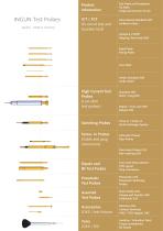
Quality - Made in Germany Product Information
Open the catalog to page 3
About INGUN INGUN – Quality through Precision A family business with persuasive know-how The family business, located in Constance at the Lake of Constance, has produced and sold test probes and test xtures all over the world since 1971, and in that fi time eveloped into the number 1 company in testing d technology. INGUN products are manufactured exclusively at the German site under the slogan Made in Germany and delivered worldwide from there. With their high precision and established know-how, INGUN would like to continue to shape the future together with you. Your competent partner since...
Open the catalog to page 4
About INGUN Worldwide in Contact INGUN UK INGUN BENELUX SWITZERLAND* INGUN TORKIYE IBERIA INGUN CHINA INGUN KOREA INGUN INDIA^ INGUN SEA Your reliable partner worldwide & INGUN co-operates with agencies worldwide and is represented all over the world with 11 of their own subsidiaries. Many of their current agencies have worked together with the test equipment specialist since the company was founded. Find your local INGUN contact person today at: www.ingun.com/contact Your local contact partner Only those who understand their customers can offer the best products and services. The INGUN group...
Open the catalog to page 5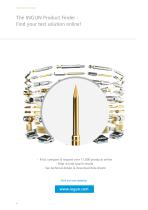
Technical Information The INGUN Product Finder Find your test solution online! - Find, compare & request over 11,000 products online - Filter & limit search results - See technical details & download data sheets
Open the catalog to page 6
Product Information Technical Information All relevant information about test probes and receptacles is featured and explained on the product information pages. INGUN offers an unbeatable range of spring-loaded test probes. Each product number has a defined key, which includes relevant information about tip style, tip diameter, spring force and material. Depending on the electronic assembly and the test points to be contacted, various test probe tip styles are available. The combination of the optimally selected test probe version and spring force enables precise, reliable and replicable contacting....
Open the catalog to page 7
Technical Information INGUN Test Probes Products and Part Number INGUN part numbers Each INGUN product number has a defined key, which includes relevant information about the probe version i.e., series, grid size, tip style, tip diameter, spring force and material. Within each series, various combinations are possible and are shown on the respective page. After selecting the individual components, such as tip style, the order number can be derived using the following system: Rotating test probe - DKS Dipole test probe - DPS Standard test probe - GKS Screw-in step probe - T 2 Series 3 Tip material...
Open the catalog to page 8
Technical Information Product Information Choice of Suitable Tip Style The choice of suitable tip style is one of the most important factors in choosing the right test probe. Many of the tip styles can be used for several applications. A basic classification can be made with respect to the geometry of the test points such as pad, via, pin or posts. Furthermore, the test point can be differentiated by its size and surface condition (oxidised, clean or contaminated by residue from the soldering process). Depending on the DUT and test conditions, it may be necessary to try several tips styles and...
Open the catalog to page 9
Tip Styles Overview Tip Style 01 (self-cleaning 30° needle tip) Commonly used, moderately aggressive tip for test pads. Tip Style 02 (flat) Very passive tip, for contacting clean test points such as test pads which should not be punctured, as well as connector and plug-in card terminals. Tip Style 03 (inverse cone) Commonly used tip for contacting connector pins and wire-wrap posts. Tip Style 04 (standard 4-point crown) One of the most commonly used tips for contacting component pins. Not recommended for unwashed PC boards, as contamination and clogging of solder-resin in the throat of the crown...
Open the catalog to page 10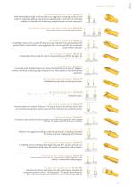
Produkt Product Informationen Information e-type Bead Probe (self-cleaning slotted inverse cone) Tip Style 19 With this modified design of the tip style 03 an aggressive contacting contour in the centre is created by applying cross grooves. Subsequently, a maximum of contacting reliability is achieved when contacting component pins and wire-wrap posts. (self-cleaning 6-point crown with higher middle point) Tip Style 24 Universally used for practically all test points. (self-cleaning 3-point crown) Tip Style 33 A modified version of the 4-point self-cleaning crown (tip style 14), manufactured...
Open the catalog to page 11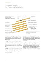
Technical Information Functional Principles Test Probes and Receptacles spring loaded test probe (GKS) and receptacle (KS) for plug-in connection (crimping points on side of the KS) spring loaded test probe (GKS) plunger tip with choice of tip style barrel spring receptacle with wire wrap post special designation “ ” 47 receptacles (KS) wire-wrap post open end with hole for inserting wire solder connection pressed or milled open-ended receptacle or soldering hole pre-wired with wrapable solid or flexible wire Spring-loaded test probes (GKS) normally consist of three individual components. These...
Open the catalog to page 12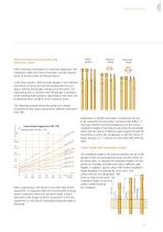
Recommended working stroke and maximum stroke Working Stroke Maximum Stroke When choosing a test probe for a particular application, the installation height, the choice of tip-style, and the required stroke of the test probe are decisive factors. In the home position, the test probe plunger is not activated, yet still has a certain pre-load; the beading then acts as a stop to prevent the plunger coming out of the barrel. The rated spring force is reached when the plunger is activated to the working stroke position. Depending on the series, this lies between 66% and 80% of the maximum stroke....
Open the catalog to page 13All INGUN Prüfmittelbau catalogs and technical brochures
 Manual Test Fixtures
2 Pages
 Board Marker Probe
2 Pages
 Battery Test Probes
4 Pages
 RF-Probes
211 Pages
 Test Fixtures
214 Pages
 Bead Probe
8 Pages