
- Catalogs
- INGUN Prüfmittelbau
- Test Fixtures


Test Fixtures

Test Fixtures
INGUN test fixtures are used across various industries for precise testing of electronic functional units. The company offers a wide range of standardized test fixtures, including manual, pneumatic, vacuum-operated, and inline exchangeable kits, along with numerous accessories. INGUN is known for its high-quality, modular test equipment made in Germany.
The document details the product range, including manual test fixtures (MA), pneumatic test fixtures (PAZ/PA), vacuum test fixtures (VA), and inline interchangeable kits (WS). Each type of fixture is designed to generate a parallel contact stroke for testing electronic devices. The fixtures are modular, allowing for customization and adaptation to specific testing needs.
INGUN provides a product finder tool online to help users find, compare, and inquire about over 11,000 products. The test fixtures are designed with a modular approach, offering flexibility and quick setup without tools. They support various signal transmission options and reliable contacting.
Test fixtures can be equipped with or without a test system interface, adaptable to all common test systems. The interface can be mounted on the bottom or rear of the fixture housing, and customizations are available to meet specific customer requirements.
INGUN test fixtures cater to different production volumes, from batch to mass production. The choice of test fixture depends on the production area and the number of versions to be tested. Stand-alone fixtures are used for fewer versions, while interchangeable kit fixtures are preferred for a larger variety.
Founded in 1971, INGUN has grown into a leading company in testing technology, with a global presence in 28 countries and 11 subsidiaries. The company emphasizes precision and quality, with all products manufactured in Germany.
This document provides detailed technical information on various test fixtures used for testing electronic units such as printed circuit boards (PCBs). It covers specifications, procedures, and materials used in the construction of these fixtures, as well as the challenges and methods involved in test fixture customization.
The document outlines different series of test fixtures, including manual (MA), pneumatic (PAZ/PA), and vacuum (VA) test fixtures. Each series is designed for specific testing needs, such as manual generation of contact strokes, automated testing using compressed air, or vacuum-powered systems for large numbers of test points. Key specifications include maximum contact force, usable area, and load cycles.
Several test methods are described, including Functional Test (FCT), In-Circuit Test (ICT), Boundary Scan Test, and Open Test. Each method targets different aspects of electronic unit testing, from checking the function of unit networks to testing individual components for errors.
Customization of test fixtures involves addressing challenges such as contacting very small test points and ensuring low stress on electronic units. The document discusses standard and precision customization options, including the use of optical inspection systems and mechanical fine adjustment tools.
High-quality materials are used to ensure performance and quality. The document emphasizes the importance of ESD-compliant materials to protect sensitive components from electrostatic discharge. It details the properties of materials like FR4, CEM-1, and acrylic glass, focusing on their elasticity, surface resistance, and temperature index.
INGUN employs state-of-the-art testing and measuring tools to ensure quality assurance. This includes multi-sensor coordinate measuring machines, wiring testers, and functional unit analysis both before and after production.
The document highlights INGUN's commitment to European Environmental Legislation, ensuring protection of human health and the environment. It lists various directives and certifications, such as RoHS and REACH, that INGUN complies with.
Manual test fixtures are divided into series MA xxx and MA xxxx, each with specific features and applications. They can be used as interchangeable or stand-alone fixtures, with modular designs allowing for expanded functionality.
Exchangeable kits for manual test fixtures are available in standard, ESD, radio frequency, and rigid pin versions. These kits can be quickly changed without tools, catering to different testing requirements such as ESD protection or high-sensitivity RF module testing.
The document provides detailed ordering information for various components and accessories related to manual interchangeable test fixtures. Key parts include the basic unit (Part no.: 45650 MA 360/F), drive unit (Part no.: 45668 ATE MA360), and exchangeable kits (Part no.: 45669-KIT ATS MA360 Standard and 46200-KIT ATS MA360/ESD ESD). Accessories such as rear panels, bottom plates, and adjustable feet are also listed with their respective part numbers.
The document outlines specifications for different models of manual interchangeable test fixtures (MA 160/F, MA 260/F, MA 350/F, MA 360/F). It includes details such as maximum contact force, parallel stroke, dimensions (both closed and open), usable area, pressure frame unit opening angle, clamping force, and operating temperature range. The fixtures are designed for batch testing of electronic units like PCBs.
The MA 20xx series is highlighted for its suitability in series testing, offering features like high contact force (up to 2,000 N), energy-saving mechanisms, and a lifespan of 500,000 load cycles under laboratory conditions. The fixtures are available with or without a test system interface and include permanently mounted exchangeable kits.
Customization options are available, with guidelines provided for tailoring exchangeable kits. Starter kits and various accessories for customization, such as pushrods and support pins, are mentioned. The document also references additional functional units and stiffener bars for extending functionality.
Instructions for setting up the test fixtures for new tasks are provided, detailing steps for inserting and removing probe plates and pressure frame plates. The document emphasizes ease of exchange and provides links to informative videos for further guidance.
- Interchangeable kit system with high contact force up to 2,000 N.
- Available with or without a test system interface.
- Energy-saving, shock-absorbing opening mechanism.
- Modular internal interface and quick installation of exchangeable kits without readjustment.
- Pressure frame unit and probe plate can be secured for storage or transport.
- Basic unit dimensions vary by model, with specific measurements provided for closed and open states.
- Pressure frame unit opening angle is approximately 75° with a clamping force of 120 N.
- Exchangeable kits have specified usable areas and free height above the PCB.
- Operating temperature range is from +10°C to +60°C.
- Contact Force: Up to 2,000 N
- Parallel Stroke: 22 mm
- Maximum Usable Area: Varies by model, up to 440 x 310 mm
- Load Cycles: 2,000,000 under laboratory conditions
- Robust drive optimized for rough test use
- Interchangeable kit system for flexibility
- Energy-saving, shock-absorbing opening mechanism
- Modularly configurable internal interface
- Quick installation of exchangeable kits without tools
- MA 3211: Closed dimensions approx. 320 x 533 x 270 mm, open dimensions approx. 320 x 464 x 637 mm
- MA 3212: Closed dimensions approx. 492 x 533 x 270 mm, open dimensions approx. 492 x 464 x 607 mm
- MA 3213: Closed dimensions approx. 648 x 601 x 270 mm, open dimensions approx. 648 x 533 x 670 mm
This document provides detailed specifications and features of manual interchangeable test fixtures and exchangeable kits, particularly focusing on RF (Radio Frequency) exchangeable kits. These kits are designed for precise and reliable testing of RF modules, ensuring interference-free measurement of high-frequency signals.
- Contact Force: 2,000 N
- Parallel Stroke: 22 mm
- Maximum Usable Area: Varies by model, up to 540 x 310 mm
- Load Cycles: 2,000,000 (under laboratory conditions)
- Operating Temperature Range: +10°C to +60°C
- Fully closed pressure frame
- Exchangeable kits available with or without internal interface
- Single-sided, double-sided, and dual-stage contacting options
- Quick installation without tools and no need for readjustment
- Outstanding screening attenuation up to 6 GHz for RF kits
- Protection against RF fields for operating personnel
- Outer Dimensions (Closed): Varies by model, e.g., MA 3213T/D/H/2x S-5: approx. 648 x 533 x 270 mm
- Pressure Frame Unit Opening Angle: Approx. 75°
- Pressure Frame Unit Clamping Force: Approx. 70 N (at full load)
- Usable Area for Exchangeable Kits: Varies by model, e.g., ATS MA11/HF: approx. 100 x 160 mm
- Free Height Above PCB: Approx. 58 mm
Part numbers are provided for various configurations of basic units and exchangeable kits, with options for standard, ESD, and RF configurations.
These kits are designed for high-frequency testing and include features such as EMC-compatible RF connectors and RF absorbers for different frequencies. They are compatible with MA 21xx and MA 32xx series test fixtures.
INGUN offers customization options, including starter kits and accessories like pushrods and PCB support pins, to tailor the test fixtures to specific needs.
- Pushrod length: 60 mm
- GKS installation height: 10.5 mm (bottom), 16.0 mm (top)
- GKS theoretical working stroke: 3 mm (bottom), 3.5 mm (top)
- Operating temperature range: +10 °C to +60 °C
- ATS MA11/S-5/HF: max. 5
- ATS MA12/S-7/HF: max. 7
- ATS MA13/S-10/HF: max. 10
Radio Frequency Exchangeable Kits:
- Part no. 54011: ATS MA11/HF RF kit without internal interface
- Part no. 54111: ATS MA11/S-5/HF RF kit with internal interface
- Part no. 54012: ATS MA12/HF RF kit without internal interface
- Part no. 54112: ATS MA12/S-7/HF RF kit with internal interface
- Part no. 54013: ATS MA13/HF RF kit without internal interface
- Part no. 54113: ATS MA13/S-10/HF RF kit with internal interface
Replacement Kits:
- Part no. 101783: ETK-HGD-ATSMA11/HF RF sealing kit
- Part no. 101784: ETK-HGD-ATSMA12/HF RF sealing kit
- Part no. 101787: ETK-HGD-ATSMA13/HF RF sealing kit
- Precision manufactured RF chambers
- Internal interface for interface blocks
- ESD paint and discharge button
- Dual-stage contacting not possible with RF kits
- Coaxial RF transfer components for minimal loss
- Impedance: 50 Ω or 75 Ω up to 18 GHz
- Low voltage and serial signals via sub-D transfer with C-filter
- USB signals require additional transfer filters for USB1 and USB2
- Bus and HSD signals up to 150 Mbps
- Used to prevent unwanted reflections within RF chamber
- Customisation reduces usable area and component height
- Available for frequencies from 2.4 GHz, 3.5 GHz, and 7.5 GHz
- Enhance functionality of manual test fixtures and exchangeable kits
- Include safety switches, self-opening units, and control boxes
- Compatibility matrix available for assembly options
- Dual-Stage Contacting: The document describes dual-stage contacting mechanisms, including electrically, pneumatically, and mechanically locked systems. These are used for ICT/FCT dual-stage contacting, with the first stage achieved when the pressure frame is closed and the second stage by lifting the handle.
- Safety Switches: Various safety switches are detailed, including those with solenoid interlocks (normally closed and open) and magnetic safety switches, designed for tests with dangerous voltages.
- Self-Opening Units: Electric and pneumatic self-opening units are described, which automatically open test fixtures and include hydraulic brake cylinders to manage opening speed.
- Locking Mechanisms: The document outlines procedures for locking pressure frame units using pneumatic short-stroke cylinders and stroke magnets, ensuring safety during tests with dangerous voltages.
- Detection Checks: Various detection checks are used to manage control tasks, such as test start, using inductive sensors and stroke switches.
- Reinforcement Strips: For installations with more than 300 test probes or forces greater than 500 N, reinforcement strips are recommended to prevent bending of probe plates.
- Protective Covers: For tests with dangerous voltages, protective covers with IP3x degree of protection are recommended to ensure safety.
- Gas Pressure Springs: Used to reduce the force of opening the housing.
- LED Indication: Pass/fail LED indicators for test results.
- Anti-Pinch Protection: Provides a safe distance to protect operators' fingers.
- PAZ xxx Series: Features gear wheel drive, high contact force up to 2,500 N, and a parallel stroke of 15 mm. Available in various models (PAZ 200, PAZ 220, PAZ 215, PAZ 400, PAZ 500) with different dimensions and contact forces.
- PA xxxx Series: Utilizes a cam disc mechanism with a contact force of 700 N and similar parallel stroke. Model PA 2130 is highlighted.
- Interchangeable kit system for ease of use and adaptability.
- Equipped with safety switches and finger guards for enhanced safety.
- Energy-saving mechanisms and tool-free exchangeable kits available in standard and ESD versions.
- Designed for extra-low voltage (PELV) and require customer-supplied pneumatic valve actuation.
- Operating temperature range: +10°C to +60°C.
- Compressed air supply requirement: 0.4 - 0.6 MPa.
- Permissible test voltage: 25 V AC / 60 V DC.
- Life span: 1,000,000 load cycles under laboratory conditions.
This document provides detailed technical specifications and features of stand-alone vacuum test fixtures designed for use with various test systems. These fixtures are robust, compatible with common test systems, and available in different versions and sizes. They are designed for single-sided, single-stage, or dual-stage contacting and are connected to existing test systems.
- Robust design compatible with all common test systems and interfaces.
- Stand-alone system without interchangeable replacement kits.
- Available in different versions and sizes with a test system interface.
- Can be used for single-sided, single-stage, or dual-stage contacting.
The life span of these fixtures exceeds 2,000,000 load cycles under laboratory conditions. However, the actual duration of use in the test field is not guaranteed due to varying factors.
Standardised customisations such as vacuum covers, pressure frame units, and additional contact units are available. Customising documents are provided for further customisation according to guidelines.
- Maximum contact force and parallel stroke details are provided in a table on page 90.
- Outer dimensions and usable area vary by model, with specific measurements provided for each.
- Operating temperature range is from +10°C to +60°C.
Various part numbers are listed for different configurations of vacuum stand-alone test fixtures, including single-stage and dual-stage contacting options.
Accessories such as pushrods, PCB support pins, tooling pins, and marking units are available from page 153 onwards.
The document provides comprehensive information on the design, specifications, and ordering details for vacuum test fixtures, ensuring compatibility with various test systems and offering customisation options to meet specific testing needs.
- Available in single-stage and dual-stage contacting configurations.
- Constructed with a 14 mm thick probe plate made of FR4 material.
- Aluminium frame housing, not hinged, ensuring durability and stability.
- Compatible with the i3070 test system interface, supporting up to 3,666 personality pins for small fixtures and 7,332 for large fixtures.
- Maximum contact force and parallel stroke details are referenced on page 90.
- Operating temperature range: +10°C to +60°C.
- Outer dimensions and usable area vary by model, with detailed measurements provided for each variant.
- Sample position and pressure frame unit opening angles are specified for different models.
- Various part numbers are provided for different configurations, including single-stage and dual-stage contacting options.
- Additional hardware such as stroke counters and swivelling contact units are available for certain models.
- Includes wire-wrap posts, spring-loaded test probes, and interface plates compatible with VA 2070S and VA 2073L fixtures.
- TestJet/VTEP components and electronics plates are available for enhanced testing capabilities.
- Recommended receptacles and installation heights are provided for TestJet/VTEP and Polarity Check applications.
- Standard and tandem versions available with or without test system interfaces.
- Probe plates are 10 mm thick, made of CEM-1 or FR4 materials.
- Single-sided, single-stage, or dual-stage contacting options.
- Dual-stage contacting includes electrically operated shifting plates.
- Maximum contact force and parallel stroke details are referenced on page 90.
- Outer dimensions and usable areas vary by model, with specific measurements provided for each VA model.
- Operating temperature range is from +10°C to +60°C.
- SPEA 501 and TD series interfaces are mentioned, with specific pin configurations and capacities.
- Interfaces are not included with the fixtures and must be ordered separately.
- Part numbers are provided for various configurations, including single and dual-stage contacting options.
- Accessories such as electric drives and spacer plates are listed with part numbers.
- Escan Multiplexer and Captor sensor plates are available for customization, with detailed specifications for each component.
- Some models are prepared for mounting multiple test system interfaces.
- ESD-compliant pressure plates and optional fully loaded interfaces are available for certain models.
- Test fixtures are available in different series and sizes, such as VA 2030, VA 2040, VA 2601-2e, etc.
- Probe plates (KTP) are made of materials like CEM-1 and FR4, with a thickness of 10 mm.
- Fixtures include grip plates or hinged handles for portability.
- Operating temperature range is from +10°C to +60°C.
- Maximum contact force and parallel stroke details are referenced to a table on page 90.
- Outer dimensions and usable areas vary by model, with specific measurements provided for each.
- Standard and tandem versions available with test system interfaces.
- Single-sided, single-stage, or dual-stage contacting options.
- Dual-stage contacting includes an electrically operated shifting plate.
- GR 228x and GR 2270/71 interfaces support a range of signal and power contact terminals.
- Interfaces are equipped with fully loaded slots, varying by model (e.g., 15 or 18 slots).
- Pylon interface supports up to 1,700 signals with suitable interface blocks available.
- Part numbers are provided for various configurations, including single-stage and dual-stage contacting options.
- Accessories such as signal and power contact terminals are available for interface re-equipping.
- Installation height and theoretical working stroke details are specified for GKS systems.
- Additional customization accessories and compatible test fixtures are listed for TERADYNE systems.
- Test fixtures are available in standard and tandem versions, with options for single-sided single-stage or dual-stage contacting.
- Probe plates (KTP) are made of CEM-1 or FR4, with thicknesses of 10 mm.
- Fixtures include grip plates, hinged handles, or bow handles for carrying.
- Maximum contact force and parallel stroke specifications are detailed in a separate table (page 90).
- Operating temperature range is from +10°C to +60°C.
- Outer dimensions and usable areas vary by model, with specific measurements provided for each fixture type.
- GKS installation height and theoretical working stroke are specified for both single and dual-stage configurations.
- Pylon interface supports up to 10 interface blocks for a maximum of 1,700 signals.
- VPC-G12-12 and VPC-G12x-18 interfaces support various configurations for signal and power modules, with capacities for up to 3,072 signals and 304 power signals.
- Part numbers are provided for each fixture and accessory, detailing the specific configurations and included components such as electric drives and interface modules.
- Accessories include vacuum flanges, interface modules, and contact terminals for signal and power transmission.
- Fixtures are designed for manual interchangeability and are compatible with various test systems, including COBHAM (AEROFLEX), DIGITALTEST, and KEYSIGHT.
- Some models include electrically operated shifting plates for dual-stage contacting.
- Dimensions vary across models, with outer dimensions and usable areas specified for each.
- Features include ESD-compliant pressure frame plates, gas pressure springs, and locking mechanisms.
- Operating temperature range is +10°C to +60°C.
- Ordering information includes part numbers and specific configurations for each model.
- Designed for mounting on VA pressure plates with ESD-compliant features.
- Specifications include outer dimensions, usable areas, and gas pressure spring configurations.
- Compatible with vacuum stand-alone test fixtures.
- Ordering information provides part numbers and specific configurations.
- ESD-compliant vacuum covers with varying wall thicknesses and dimensions.
- Features include snap-on fasteners and gas pressure springs.
- Compatible with specific vacuum test fixtures.
- Ordering information includes part numbers and configurations.
- Designed for single-stage top contact with ESD-compliant probe plates.
- Specifications include outer dimensions, usable areas, and precision guides.
- Compatible with vacuum stand-alone test fixtures.
- Ordering information provides part numbers and specific configurations.
- Common specifications include opening angles, pushrod lengths, and free height above PCB.
- Operating temperature range is consistent across components.
- Options for vacuum-free zones and specific test fixture compatibility.
- Customizations are available for complex printed circuit boards and single-stage top contacting.
Signal blocks (SB) are designed for reliable signal transmission between test devices and systems across various interfaces, including internal, external, and customer-specific. They support different types of signals such as high current, radio frequency, fibre optic, and more.
Signal transmission is achieved between two interface blocks with a working distance of 15.1 ±0.5 mm. One block is equipped with spring-loaded test probes, while the other has rigid contact terminals or couplings. This setup ensures high contact quality and low contact resistance.
- Compact and robust design
- Reliable signal transmission
- High contact/transmission quality
- Uniformly low contact resistance
- Supports various interfaces
- Easy and precise mounting
The life span varies by model, with SB-T/P-SI-… lasting 300,000 cycles and SB-T/P-HS-… lasting 80,000 cycles under laboratory conditions.
Standard Signal Blocks
- Working distance: 15.1 ± 0.5 mm
- Working stroke: 2.6 mm
- Contact resistance: 20 mΩ
- Operating temperature: -30°C to +80°C
- RoHS compliant
- Working stroke: 4.0 mm
- Contact resistance: < 10 mΩ
These blocks are used for high current transmission up to 50 A. They are available with or without centring and have a contact resistance of ≤ 10 mΩ.
Signal and high current blocks can be customised with various pole numbers and configurations to meet specific requirements.
Detailed ordering information is provided for both signal and high current blocks, including part numbers, specifications, and configurations.
Signal blocks are suitable for low-voltage and dangerous voltage applications, while high current blocks are designed for high current and dangerous voltage transmission. Radio frequency blocks support signal transmission up to 0.7 GHz.
Radio Frequency Blocks (up to 0.7 GHz)
- Working distance: 15.1 ± 0.5 mm
- Working stroke: 4.0 mm
- Spring force: up to 48 N
- Frequency range: up to 0.7 GHz
- Impedance: 50 Ω
- Operating temperature: -30 °C to +80 °C
- Connection: Plug SE-...
- RoHS compliant
- Similar specifications as 0.7 GHz blocks but with a spring force up to 84.8 N and centring range of ± 0.3 mm.
- Frequency range extended to 4 GHz with similar specifications as 2 GHz blocks.
- Up to 6 GHz: Spring force up to 42.4 N, centring range ± 0.3 mm.
- Up to 18 GHz: No centring, operating temperature 0 °C to +80 °C.
- Used for optical signal transmission, primarily for testing LEDs.
- Working distance: 15.1 ± 0.5 mm
- Operating temperature: -30 °C to +80 °C
- RoHS compliant
- Various configurations for different fibre optic cable diameters.
- Detailed part numbers and configurations for both test system side and DUT side blocks are provided for each frequency range and type.
- Blocks can be customized with different numbers of poles and loaded with RF probes or contact terminals as needed.
- Accessories and mounting materials are included, but SE-... plugs and fibre optic cables are ordered separately.
Interface blocks are categorized into those mounted on the test system side (SB-T-…) and those on the DUT side (SB-P-…). They consist of spring-loaded test probes and rigid contact terminals or pneumatic/fiber optic cable couplings. The power loss and air distance calculations are crucial to ensure the current and voltage do not exceed specified limits. For example, a 170-pole low-impedance interface block can handle a maximum current of 4 A per test probe and a maximum voltage of 270 V with an air distance of 0.34 mm.
Marking units are used for permanent marking of PC boards. They are available in electrical (ME-E) and pneumatic (ME-P) versions. The electrical units use a 12 V DC electric gear motor, while the pneumatic units use compressed air. Both types offer compact, robust designs with precise positioning and are suitable for various materials. The life span of ME-E units is 500,000 cycles, and ME-P units is 150,000 cycles under laboratory conditions.
Electrical marking units have dimensions of approximately ∅ 12 × 60 mm to ∅ 12 × 100 mm, with a drive connection via cable or plug connector. Pneumatic units have dimensions of ∅ 16 × 54 mm and use a compressed air connection. Both types have specific marking heads and materials they are compatible with, such as hard and soft materials.
Installation requires precise alignment and mounting using specified threads and nuts. Accessories include spare part engraver kits and suction devices to minimize contamination during marking. For electrical units, a current limit of 100 mA is recommended to prevent damage. Pneumatic units emit high-frequency noise, which can be reduced using a silencer.
- Installation: Includes components like silencer and suction devices to reduce noise emissions by approximately 7 dB. Compatible with specific parts and operates at a pressure of 0.6 MPa.
- Components: Includes pushrod, PCB support pin, spring-loaded marking engraver, and more.
- Specifications: Outer dimensions and operating pressure are specified for different components.
- Specifications: Details on dimensions, weight, operating temperature, and drive connection. Marking heads are made of solid carbide with a hardness of approximately 1,600 HV.
- Performance: Recommended working stroke and marking impulse are provided, along with force at working stroke.
- Compliance: Units are RoHS and CE compliant.
- Comparison: INGUN marking units are compared with competitors based on mechanical/electrical lifespan, design, delivery, and costs. Results are graded on a scale from 1 (very good) to 6 (inadequate).
- Types: Stroke-controlled (SAM-H), manual (SAM-M), and pneumatic (SAM-P) mechanisms are available for reliable contacting of electronic components.
- Features: Compact design, stable precision guidance, and long lifespan with up to 300,000 load cycles.
- Specifications: Detailed specifications for each type, including contact force, stroke, and operating conditions.
1. Dimensions: 82 × 105 × 28 mm
2. Weight: Approx. 0.58 kg
3. Proximity Switch: SME-8-K-LED-24
4. Valve Assembly: 5/2 monostable, Operating Pressure: 0.1 to 1 MPa, Pneumatic Connection: M5, Rated Operating Voltage: 24 V DC, Display: LED
5. Delivery Includes: Magnet valve 5/2-24 V DC, Power outlet cable, Push-in fitting, Silencer, Compressed air hose (PUN-4x0,75-BL, length approx. 1 m)
1. Partly completed machinery in accordance with 2006/42/EC
2. Pneumatic side approach mechanisms (SAM-P) with contact force 68 N and contact stroke 50 mm
1. Side contacting with pneumatic side approach mechanism (SAM-P)
2. Proximity switch (part 25638)
3. Valve assembly (part 42702) includes magnet valve, power outlet cable, push-in fitting, silencer
1. Types: Stroke-controlled, Manual, Pneumatic
2. Series: SAM-H, SAM-M, SAM-P
3. Maximum Contact Force: Ranges from 68 N to 300 N
4. Maximum Contact Stroke: Ranges from 14 mm to 50 mm
5. Operating Temperature Range: -5 °C to +60 °C
1. Connectors (STK) and Test Plugs (PS) for reliable, low-wear contacting
2. Connectors: STK-X,XX, STK-USB
3. Test Plugs: PS-RJ, PS
4. Features: Floating mount, Precise, low-wear, self-centring contacting, Modular design, Outstanding lifespan
1. Connectors (STK) for SMC plug connectors
2. Test Plugs (PS) for digital phone and network plug connectors
3. Screwing Units (SBE) for space-saving alignment of adjustable screw-in devices
- Available in standard and airtight designs with manual activation.
- Strokes range from 4 mm to 35 mm, with mounting grids of 8 mm, 15 mm, and 18 mm.
- Rotary knobs made from POM or aluminium, with options for slotted, cross slot, and round bits.
- Flexible shaft design available, activated by a step motor.
- Used for activating buttons and switches during testing.
- Manual activation with strokes of 8 mm and mounting grids of 10 mm or 12 mm.
- Low voltage-compliant versions available.
- Used to secure electronic PCBs against test probe forces.
- Available in rigid (one-part/two-part) and spring-loaded designs.
- Various mounting options: screw-in, plug-in, and press-in.
- Facilitate signal transmission during testing.
- Spring-loaded design allows for easy removal without disrupting wiring.
- Available in various sizes and connection types (solder, wire wrap).
- Support PCBs during testing, mounted on moving plates.
- Available in various tip style diameters and lengths.
- Suitable for ESD protected areas.
- Components are designed for quick and simple mounting.
- Customisation options available for specific applications.
- Technical specifications include dimensions, materials, and mounting details.
1. PAS Series PCB Support Pins:
- Tip lengths: 2.8 mm and 5.8 mm
- Tip diameters: 3.0 mm, 4.0 mm, and 5.0 mm
- Total heights: 6.8 mm and 10.8 mm
- Materials: PA 6 granulate mixture and FR4
- Mounting: Press in
- Tip lengths: 6.0 mm and 7.0 mm
- Design: Rigid, round
- Mounting: Press in
- Materials: Stainless steel, available in non-hardened or hardened versions
- Types: Round and sword-shaped
- Mounting: Crimped onto probe plate or onto moving plate
- Features: High-precision, low-wear, carbide head material
- Types: Centric and eccentric
- Diameters: 6 mm, 8 mm, 10 mm, 12 mm
- Mounting: Screw in
- Materials: POM (natural or black), antistatic versions available
- Type: Pressure spring
- Diameters: 10 mm, 11.6 mm, 12 mm, 12.1 mm
- Mounting: Press in
- Features: Various lengths and forces
- Usage: Counterbalance weights, supportive opening and holding mechanisms
- Features: Various lengths and forces, typical lifespan of approx. 50,000 load cycles
- Tooling pins are used to mount and position PCBs precisely in the probe field.
- Spring-loaded tooling pins are mounted on either the probe plate or moving plate, depending on design.
- Pre-centring pins are used as insertion aids to pre-position DUTs on the probe field.
- Springs are used to lift the probe plate with the DUT back to the original level after contacting.
- Gas pressure springs are used in test fixtures for supportive opening and holding mechanisms.
- Detailed part numbers and specifications are provided for each type of pin and spring, allowing for customization based on specific requirements.
Various models of gas pressure springs are listed with specifications including stroke length (40 to 120 mm) and force (50 to 300 N). Some models feature dynamic shock absorption.
Includes bearing blocks, housing and cover mountings, and SL retainers for fixing gas pressure springs.
Used for electrical signal transmission in low-voltage applications. Available in 64 and 96 poles, with wire wrap or solder connections. Compliant with DIN 41612 (IEC 60603-2).
Used for cleaning test probe tips, made from a silicone/quartz powder mixture. Recommended for sharp tip styles and can handle approximately 1,000 penetration cycles.
Includes guide bushes, guide pins, stroke-limiting disks/pins, and ESD kits for dissipating electrostatic charge.
Stroke sensors detect states in test fixtures, while stroke counters are used as batch counters with external/manual resetting.
Fibre optic cables are available in different specifications for cladding and core diameters. Compressed air hoses are available with specific outer diameters and operating temperature ranges.
Catalog excerpts

Test Probes • Test Fixtures
Open the catalog to page 1
Aviation and space technology INGUN test fixtures are used by our customers in various industries and enable precise, accurarately repeatable testing of electronic functional units. As a leading company, INGUN offers standardised test fixtures for all common test systems - from manual, pneumatic and vacuum-operated test fixtures to inline exchangeable kits - and an unmatched variety of test fixture accessories. Well-known customers rely on the high quality standard - Made in Germany - and appreciate the high modularity of standardised test equipment. There is certainly a test fixture for your...
Open the catalog to page 2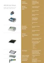
Product information
Open the catalog to page 3
About INGUN INGUN – Quality through precision A family business with persuasive know-how The family business, located in Constance at the Lake of Constance, has produced and sold test probes and test fixtures all over the world since 1971, and in that time developed into the number 1 company in testing technology. INGUN products are manufactured exclusively at the German site under the slogan MADE IN GERMANY, and delivered worldwide from there. With their high precision and established know-how, INGUN would like to continue to shape the future together with you. Your competent partner since 1971...
Open the catalog to page 4
About INGUN Worldwide in contact INGUN UK INGUN BENELUX SWITZERLAND* INGUN TORKIYE IBERIA INGUN CHINA INGUN KOREA INGUN INDIA^ INGUN SEA Your reliable partner worldwide & INGUN is represented worldwide by agencies and 11 of thier own subsidiaries. Many of their current agencies have worked together with the test equipment specialist since the company was founded. Find your contact person now: www.ingun.com/contact Your local contact partner Only those who understand their customers can offer the best products and services. The INGUN group can be reached via one of their many subsidiaries and...
Open the catalog to page 5
Technical information The INGUN Product Finder Find your individual test solution online! - Find, compare & inquire about 11,000 products online - Filter targeted & limit search results - See technical details & download data sheets
Open the catalog to page 6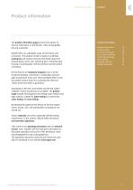
Technical information Product information Product information The product information pages present and explain all relevant information on test fixtures, inline exchangeable kits and accessories. INGUN offers an unbeatable range of test fixtures and accessories. The product number is based on a defined naming key and contains relevant information about the product group, series, size, operating type, contacting type, housing, mounting plate, internal interface and test system connection. All test fixtures are modularly designed, have a similar functional principle, and feature a probe plate,...
Open the catalog to page 7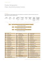
Technical information Naming key The naming key for product designation allows clear identification and classification of INGUN test fixtures thanks to the logical structure using their individual features. Housing (D = desk, F = flat) Mounting plate (H = hinged) Manual test fixture (example) Pneumatic test fixture (example) Jl'lMMMMI Vacuum test fixture (example) Common abbreviations © INGUN Prufmittelbau GmbH, Errors and technical changes reserved, as of 09/2018
Open the catalog to page 8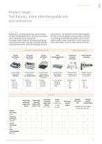
Technical information Product information Product range -Test fixtures, Inline interchangeable kits and accessories Product range INGUN offers a versatile product range with test fixtures and inline interchangeable kits for all common test systems and an unbeatable variety of accessories. The product range includes the following product groups: manual test fixture (MA), pneumatic test fixture (PAZ/PA), vacuum test fixture (VA), inline interchangeable kits (WS) and accessories. The test fixture and inline interchangeable kits differ in how the parallel contacting stroke is generated for contacting...
Open the catalog to page 9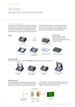
Technical information Test fixture Design and functional principle Design and functional principle Test fixtures are available as interchangeable kit and standalone test fixture. Interchangeable kit test fixtures offer the advantage of testing different exchangeable kits with just one basic unit. All test fixtures and exchangeable kits are modular and have a similar functional principle to generate the parallel contact stroke for contacting the device under test (DUT). The test fixtures consist of a housing unit (P/ FGH) and a drive unit (ATE), the exchangeable kits from a pressure frame unit...
Open the catalog to page 10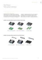
Product information Technical information Test fixture Test system interface Connection of the test system interface INGUN test fixtures are available with and without test system interface for all common test systems. Depending on the test system used, the test system interface is attached to the bottom or rear of the housing. All test adapters are available as a standard test fixture kit and can be customised according to customer’s specifications. In general, all test system interfaces can be connected. Contact us if your test system interface is not available as a standard test fixture kit....
Open the catalog to page 11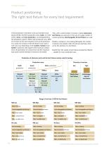
Technical information In the production of electronic units such printed circuit boards (PCBs), the three production areas, batch, (or small series), series, and mass production, are distinguished by the production volume. Within each production area, different versions of the same electronic unit can be produced. As a result, the versions of the test fixture to be used in each case vary depending on the number of pieces to be tested in particular with regard to the maximum contact force, the generation of contact force and the maximum load cycles and the diversity of versions to be tested. Thus,...
Open the catalog to page 12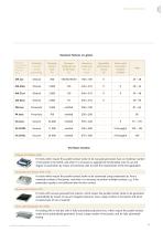
Product information Technical information Maximum Features at a glance For tests which require the parallel contact stroke to be manually generated, have an moderate number of test points to be tested, and when it is necessary to upgrade the functionality, ease of use and degree of automation by means of functional units to meet the requirements of the test application. For tests which require the parallel contact stroke to be automated using compressed air, have a moderate number of test points, and when it is necessary to perform multiple contacts, e.g. if the penetration quality is not sufficient...
Open the catalog to page 13All INGUN Prüfmittelbau catalogs and technical brochures
 Manual Test Fixtures
2 Pages
 Board Marker Probe
2 Pages
 Battery Test Probes
4 Pages
 RF-Probes
211 Pages
 Test Probes
200 Pages
 Bead Probe
8 Pages