
- Catalogs
- Ingersoll Cutting Tools
- Milling Section


Milling Section

Milling Section
Document Overview
This technical document provides comprehensive specifications, grades, tool series, inserts, hardware, and operating guidelines for a wide range of cutting tools used primarily in milling and steel machining applications. It covers tool grades, insert types, cutter dimensions, machining parameters, and best practices to optimize tool life and machining performance.
1. Grades and Applications
The "Gold Rush" series grades are detailed with specific coatings and treatments for enhanced wear resistance and toughness. Key grades include:
- IN2510 (PVD): High wear resistance for gray and ductile cast iron, suited for medium/low speed machining.
- IN2540 (PVD): For alloy, mold, and normal steels; excels in dry milling and medium to rough machining.
- IN6530 (CVD): Balances toughness and wear resistance for roughing steels, alloy, and stainless steels.
- IN2505 (PVD): Combines wear resistance and toughness for low carbon, alloy, mold, and stainless steels in medium to finish machining.
- IN2530 (PVD): Designed for steel and stainless steel at medium to low speeds.
Advanced PVD and CVD coatings improve tool life, reduce friction, and enhance surface finish quality.
2. Tool Series and Specifications
Multiple tool series are described with detailed dimensional data and application notes:
- Series 12S1X, 12S1E: Center cutting endmills with diameters from 1.000" to 1.500", various flute counts, max depth of cut, extension lengths, and insert sizes.
- Series 1KJ1_ and 1KJ1_ (TopOn): 0-degree lead endmills with insert counts, ramp angles, and insert series specified.
- Series KJ: 0-degree lead facemills with 6 indexes, detailing bore diameter, retention bolts, coolant options, and insert series.
- Series 1DJ1F, 1DJ1P and TopOn variants: 0-degree lead endmills with 6 indexes, cutter dimensions, and insert series.
- Series DJ_F, DJ_P: 0-degree lead facemills with 6 indexes, including bore diameter, keyway, retention bolts, and insert series.
3. Inserts and Hardware
Insert specifications include part numbers, corner radii (.015" to .125"), applications (multi-purpose, high-temperature, aluminum polishing), and compatible grades matching tool grades for optimized performance. Hardware such as screwdrivers (SM35-076-10 DS-T10T for 12mm, SM40-093-20 DS-T15T for 18mm) is specified for installation and maintenance.
4. Operating Guidelines
- Ramp angles and maximum depth of cut vary by tool series and insert radius, typically from 0.275" to 0.590" cut depths.
- Coolant options include through-coolant designs or no coolant capability depending on tool series.
- Side inserts with corner radii no larger than 0.031" are recommended for certain series.
5. Performance Benefits
- Extended and stable tool life in continuous and interrupted cuts.
- Reduced cutting friction and minimized built-up edge, especially on exotic materials.
- High surface finish quality and improved insert adhesion and chipping resistance.
6. Technical Summary of Milling Cutters and Inserts
6.1 Insert Specifications and Grades
Inserts vary by corner radius (.015" to .062") and application (multi-purpose, aluminum polishing, high-temperature). Grades include IN2505, IN2510, IN2530, IN2540, IN10K, IN6515, and IN70N, tailored for specific materials and machining conditions.
6.2 Cutter Series and Dimensions
Series such as 25J3P, DJ6T/DJ5T, ON5H/ON6H, OP1N, OP6N, and 1DG1H are detailed with parameters like effective diameter (D1), bore diameter (D2), keyway size (K), height (H), length of cut (L1), extension length (L2), and number of inserts, critical for selecting appropriate cutters.
6.3 Cutter Types and Lead Angles
- 0° Lead Extended Flute Shell and End Mills (Series 25J3P)
- 0° Lead Facemills with 6 or 8 indexes (Series DJ6T, DJ5T)
- 45° Lead Facemills with 16 indexes (Series ON5H, ON6H, OP1N, OP6N)
- High Feed Endmills with 4 or 6 indexes (Series 1DG1H, 1TG1F)
6.4 Insert Geometry and Application Notes
Insert geometries include positive geometry, wiper flats (improving surface finish by ~20 points), flat top, keen edge, anti-notch, faceted corners, and silicon nitride materials. Inserts target steel, iron, titanium, aluminum, non-ferrous metals, and high-temperature alloys.
6.5 Hardware and Accessories
Retention bolts, screwdrivers, torque wrenches, insert driver blades, and optional torque bits are specified to ensure secure insert installation and maintenance.
6.6 Operating Guidelines and Limitations
Maximum depth of cut (DOC) ranges from .078" for high feed endmills to .20" for facemills. Ramp angles and coolant through options influence machining efficiency and tool life.
6.7 Summary of Key Parameters
| Parameter | Typical Values | Notes |
|---|---|---|
| Insert Corner Radius | .015" to .250" | Varies by application and material |
| Number of Inserts | 2 to 38 | Depends on cutter size and series |
| Effective Diameter (D1) | 1.25" to 12.00" | Determines cutting width |
| Lead Angle | 0°, 45° | Influences cutting forces and finish |
| Max Depth of Cut (DOC) | .078" to .20" | Specified per cutter series |
| Coolant Options | Through coolant available on many cutters | Improves cooling and chip evacuation |
6.8 Recommendations and Best Practices
- Use wiper inserts to enhance surface finish within specified feed per revolution limits.
- Select insert grade and geometry based on workpiece material and machining conditions.
- Adhere to maximum depth of cut and ramp angle guidelines to optimize tool life and performance.
- Utilize appropriate hardware and torque tools for secure insert retention.
- Consult detailed operating guidelines for machining parameters and procedures.
7. Technical Summary of High Feed Milling Cutters and Inserts
7.1 Series DG6H - High Feed Facemill with 6 Indexes
Facemills designed for high feed rates with 6 indexable inserts, bore diameters 2.0 to 6.0 inches, ramp angles 0.2° to 1.0°, max DOC 0.078", and coolant capabilities including plunging and ramping. Compatible inserts include grades IN2530, IN2505, IN2540, and IN6530 with 0.118" radius.
7.2 Series 1TG1F - High Feed Endmill with 4 Indexes
Endmills with diameters 0.625" to 1.5", extensions up to 6.25", max DOC 0.027" to 0.039", ramp angles 0.5° to 1.5°, and coolant features for various milling operations.
7.3 Series TG1F - High Feed Facemill with 4 Indexes
Facemills with 4 inserts, bore diameter ~0.75", ramp angles up to 0.3°, supporting coolant channeling and multiple milling operations.
7.4 Series 15M1P and 5M_P - 13mm Inserted Cutters, High Feed
Cutters with 13mm inserts for high feed milling, diameters from 1.25" to 5.0", multiple inserts (2 to 11), ramp angles 0.4° to 5.6°, coolant through capability, and both Weldon and cylindrical shanks.
7.5 Series 5G_M - 19mm Inserted Cutters, High Feed
19mm insert cutters with diameters 3.0" to 6.0", 5 to 10 inserts, ramp angles 0.4° to 1.6°, and optional coolant through capability.
7.6 Inserts and Hardware
Insert grades include IN2505, IN2530, IN4030, IN4035, and IN4005 with corner radii 0.031" to 0.147" and max DOC 0.078" to 0.147". Hardware includes retention bolts, coolant bolts, screwdrivers, and driver bits.
7.7 Series QHU - Backdraft Plunge Cutters
Plunge cutters with coolant and backdraft features, bore diameters 2.0" to 4.0", ramp angles 2°, and optional retention and coolant bolts.
7.8 Critical Information and Recommendations
- Max DOC ranges from 0.027" to 0.147" depending on series.
- Ramp angles critical for performance, ranging 0.2° to 5.6°.
- Coolant through capability enhances tool life and machining quality.
- Proper insert grade and corner radius selection essential for application.
- Consult operating guidelines for detailed instructions.
8. Additional Tool Series and Hardware
Includes series DD6H (high feed facemills with 8 indexes), 1TJ1Q (0° lead endmills), TJ5Q/TJ6Q (0° lead facemills), 1TJ1N, TJ5N/TJ6N, TN1N (45° lead facemills), 15B1B and 1A7_ (button cutters), 1DE1H and DE6H (button endmills and facemills), and 12A9/12A5 (ball nose endmills). Detailed dimensions, insert compatibility, coolant options, and ramp angles are provided.
9. Ball Nose and Slotter Cutters
Series 12A8 (ball nose taper steel cutter bodies), 2TW7K (ball nose endmills), EF6J (finishing facemills), VJ6K (0° lead facemills), 3EJ6 and 3VJ5V (axial and radial drive slotters) are described with insert series, corner radii, and hardware specifications.
10. Machining Parameters and Material Guidelines
Detailed machining parameters for materials including aluminum alloys, cast iron (gray and nodular), steels (low/high carbon, alloyed, tool), stainless steels (300 and 400 series), nickel alloys, and titanium are provided. Parameters include Brinell hardness, surface feet per minute (SFM), feed per insert, width of cut (WOC), and coolant recommendations.
| Material | Brinell Hardness | SFM Range | Feed per Insert (inches) | Coolant Recommended |
|---|---|---|---|---|
| Aluminum | – | 1000 - 10000 | 0.004 - 0.018 | Yes |
| Cast Iron (Gray) | 150 - 250 | 300 - 1000 | 0.004 - 0.010 | No |
| Cast Iron (Nodular) | 300 - 800 | 300 - 1000 | 0.004 - 0.010 | No |
| Steel (Low Carbon) | 150 - 250 | 400 - 1000 | 0.004 - 0.010 | No |
| Steel (High Carbon) | 250 - 400 | 350 - 500 | 0.004 - 0.008 | No |
| Alloyed Steel | 150 - 300 | 300 - 700 | 0.004 - 0.010 | No |
| Tool Steel | Up to 300 | 300 - 700 | 0.004 - 0.010 | No |
| Stainless Steel (300 Series) | – | 300 - 700 | 0.004 - 0.010 | May not be required at high speeds |
| Stainless Steel (400 Series, 13-8 PH) | Up to 320 | 200 - 400 | 0.004 - 0.010 | Yes |
| Nickel Alloys | 75 - 120 | 75 - 120 | 0.003 - 0.006 | Yes |
| Titanium 6AL-4V | 100 - 150 | 100 - 150 | 0.004 - 0.008 | Yes |
11. Feed Rate Guidelines Based on Width of Cut (WOC)
Starting feed rates for extended flute mills vary by material and radial width of cut, expressed as fractions of tool diameter. For example, aluminum alloys have feed rates from 0.010 to 0.015 inches depending on WOC, while steels and cast irons have lower feed rates.
12. Coolant Usage Recommendations
- Coolant is generally recommended for aluminum, nickel alloys, and titanium to improve tool life and surface finish.
- For cast iron and many steels, coolant is often not required, especially at higher speeds.
- Stainless steel coolant use depends on speed and grade; may be optional or recommended.
13. Best Practices and Notes
- Feed and speed values are starting points; optimize based on machining conditions.
- Depth and width of cut significantly affect optimal parameters.
- Adjust feeds and speeds to balance tool life, surface finish, and productivity.
- Use specific inserts (e.g., IN2006) for hardened steels above 58 Rc.
Summary
This document serves as a detailed technical reference for selecting, configuring, and operating milling cutters, facemills, endmills, and button cutters with indexed inserts. It provides critical information on tool grades, insert compatibility, cutter dimensions, machining parameters, hardware requirements, and best practices to maximize tool life and machining quality across a broad range of materials and applications.
Catalog excerpts

GOLD•RUSH grades for steel applications
Open the catalog to page 1
Grades The ingenious solution that takes cutting tool materials to another level Stable and extended tool life in continuous and interrupted cutting operations Reduced cutting friction and minimized built-up edge on exotic materials High surface finish on the workpiece Improved adhesion and insert chipping resistance STEEL CAST IRON Cutting speed IN1030 IN2530 Gray Cast Iron Ductile Cast Iron Feed rate
Open the catalog to page 3
Gold Rush Grades for Milling Applications IN2510 (PVD) Grade with high wear resistance for general cast iron machining (Gray and Ductile cast iron milling) Extended tool life for medium and low speed machining Dedicated substrate for cast iron plus PVD coated grade with surface treatment after coating Excellent for alloy steels, mold steels and normal steels Has high wear, thermal crack resistance and high mechanical shock resistance Recommended for dry milling For medium to rough machining in Die & Mold application New yellow colored PVD coated grade with surface treatment after coating IN6530...
Open the catalog to page 4
SERIES 12S1X, 12S1E CENTER CUTTING ENDMILL Facing Cutter Number Insert Size *Overall Length is measured to the sharp corner of the insert. † Use side inserts with corner radii no larger tham .031“R. Operating Guidelines on page 90.
Open the catalog to page 5
Part Number
Open the catalog to page 6
Part Number
Open the catalog to page 7
SERIES 1KJ1_ 0 DEGREE LEAD ENDMILL Shoulder Cutter Number Ramp Angle Using .031” R Insert Insert Series Operating Guidelines on page 91-92.
Open the catalog to page 9
SERIES 1KJ1_ (TOP•ON STYLE) 0 DEGREE LEAD ENDMILL Shoulder Cutter Number Wrench Size Ramp Angle Using .031” R Insert Insert Series * 3º Dovetail Endmill Operating Guidelines on page 91-92.
Open the catalog to page 10
SERIES KJ 0 DEGREE LEAD FACEMILL Shoulder Cutter Number Retention Bolt Optional Coolant Bolt Ramp Angle Using .031” R Insert Insert Series Operating Guidelines on page 91-92.
Open the catalog to page 11
Part Number Multi-Purpose, Ground Periphery Multi-Purpose, Ground Periphery Multi-Purpose, Ground Periphery Insert Screw
Open the catalog to page 12
SERIES 1DJ1F, 1DJ1P 0 DEGREE LEAD ENDMILL WITH 6 INDEXES Shoulder Cutter Number Insert Series Cutter Number Insert Series Operating Guidelines on page 92.
Open the catalog to page 13
SERIES 1DJ1F, 1DJ1P (TOP•ON STYLE) 0 DEGREE LEAD ENDMILL WITH 6 INDEXES Shoulder Cutter Number Wrench Size Insert Series Cutter Number Insert Series Wrench Size Operating Guidelines on page 92.
Open the catalog to page 14
SERIES DJ_F, DJ_P 0 DEGREE LEAD FACEMILL WITH 6 INDEXES Shoulder Cutter Number Retention Bolt Optional Coolant Bolt Insert Series Cutter Number Retention Bolt Optional Coolant Bolt Insert Series * No Coolant Through Operating Guidelines on page 92. Insert Screw
Open the catalog to page 15
Multi-Purpose - .062” R .514 WNGU13..04 Grd/Pol for Aluminum - .015” R Part Number Multi-Purpose - .062” R Grd/Pol for Aluminum - .015” R WNGU09..16 .365 Grd/Pol for Aluminum - .031” R Part Number
Open the catalog to page 16
LONG EDGE CUTTERS Extreme efficiency with most positive geometry in the market. Inserts offered with keen hi-temp and durable fiat face geometries. Internal coolant supply. Well suited for Stainless Steel and Hi Temp Alloys. 0 DEGREE LEAD EXT. FLUTE SHELL MILL Cutter Number Facing Slabbing Channel^ Operating Guidelines on page 93.
Open the catalog to page 17
SERIES 25J3P 0 DEGREE LEAD EXT. FLUTE END MILL Shoulder Cutter Number Operating Guidelines on page 93. INSERTS SDMS R Part Number Application Indexes Corner *Cutter body to be relieved to accommodate large radius. Side Station Options Insert Screw Driver Handle Insert Driver Blade Optional Torque Wrench Optional Insert Driver Blade
Open the catalog to page 18
• 8 Positive cutting edges with 90 degree shoulder • .24" Depth of cut along 90 degree shoulder • Medium and High Density cutter offerings • Cutters equipped with coolant through 0 DEGREE LEAD FACEMILL WITH 8 INDEXES Cutter Number Medium Density Operating Guidelines on page 94. lEEiBSUB mmmm
Open the catalog to page 19
SNGU ... ANTN SNGU...ANTN (Wiper w/chamfer) .47 SNGU ... ANTN Part Number SNGU ... ANTN Positive Geometry Positive Geometry Positive Geometry SNGU...N (Only corner) Insert Screw Optional Torque Wrench
Open the catalog to page 20
SERIES ON5H ON6H 45 DEGREE LEAD FACE MILL (SCREW HELD - 5MM INSERT) WITH 16 INDEXES Lead Angle Cutter Number Operating Guidelines on page 94.
Open the catalog to page 21
Part Number Medium, pos. rake angle Grd/Pol for Al Positive Geometry Retention Bolt (Optional) Coolant Bolt
Open the catalog to page 22
05 SERIES INSERTS Cutter Series: ON5H/ON6H Insert Series: ONCU05 1.50-6.00 Dia. Range .12 DOC - 45 Degree Lead Part Number MULTI-PURPOSE Universal insert geometry with landed edge. Integrated wiper flat for surface finishes between RA32-63. Whether it's steel, iron or titanium, this is an excellent first choice. MULTI-PURPOSE WIPER Wiper Insert with 8 indexes (4RH, 4LH) and longer wiper flats. When the advance per revolution does not exceed .094", place one wiper insert in one pocket to improve your surface finish by about 20 points. The indentation on the flank marks the edges that should contact...
Open the catalog to page 23
SERIES OP1N 45 DEGREE LEAD FACE MILL (WEDGE HELD - 9MM INSERT) WITH 16 INDEXES Lead Angle Cutter Number Bolt Circle Operating Guidelines on page 94. Retention Bolt Adjusting Screw
Open the catalog to page 24
SERIES OP6N 45 DEGREE LEAD FACE MILL (SCREW HELD - 9MM INSERT) WITH 16 INDEXES Lead Angle Cutter Number Bolt Circle Operating Guidelines on page 94. Retention Bolt (Optional) Coolant Bolt
Open the catalog to page 25
Part Number Positive Geometry
Open the catalog to page 26
09 SERIES INSERTS Cutter Series: OP6N RH Insert Series: ONC_09 2.50-12.00 Dia. Range .20 DOC 45 Degree Lead Part Number Cutter Series: OP1N RH&LH Insert Series: ONC_09 3.00-12.00 Dia. Range .20 DOC 45 Degree Lead MULTI-PURPOSE Universal insert with landed edge for machining steels, iron and hi-temp alloys. Also equipped with an integrated wiper flat to produce surface finishes between RA32-63. First choice for most applications. R.047 Indent .157” Crowned Wiper MULTI-PURPOSE WIPER Wiper Insert with 8 indexes (4RH, 4LH) and longer wiper flats. When the advance per revolution does not exceed .157",...
Open the catalog to page 27
09 SERIES INSERTS Cutter Series: OP6N RH Insert Series: ONC_09 2.50-12.00 Dia. Range .20 DOC 45 Degree Lead Part Number Cutter Series: OP1N RH&LH Insert Series: ONC_09 3.00-12.00 Dia. Range .20 DOC 45 Degree Lead FACETED MULTI-PURPOSE A faceted corner with positive geometry helps avoid Faceted breakout on an iron workpiece. The landed edge adds strength. FACETED WIPER Wiper Insert with 8 indexes (4RH, 4LH) and longer wiper flats. When the advance per revolution does not exceed .152", place one wiper insert in one pocket Faceted to improve your surface finish by about 20 points. The indentation...
Open the catalog to page 28All Ingersoll Cutting Tools catalogs and technical brochures
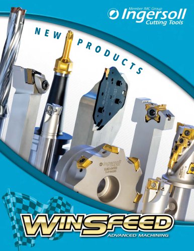 NEW PRODUCTS
176 Pages
 Hole Making
124 Pages
 Turning
57 Pages
 Slotters
16 Pages
 Solid Carbide
64 Pages
 END MILLS
58 Pages
 Gold-Rush Catalog
13 Pages
 HI-POS+
45 Pages
 quadtwist
11 Pages
 GOLD RUSH
12 Pages
 gold max 4 slotters
5 Pages
 EVOTEC Series 1SJ1Y
4 Pages
 gold max 4
3 Pages
 gold max 4 New
3 Pages
 Plunge Cutters
20 Pages
 ChipSurfer & Solid Carbide Cat.
116 Pages
 IT.TE.DI. PCD/CBN MILLING
68 Pages
 Holemaking Section
46 Pages
 Turning Section
160 Pages
 Fine Gold
302 Pages
 D'Andrea Precision Boring (INCH)
187 Pages
 Form-Master Pro
6 Pages
 Form-Master Cera Brochure
4 Pages
 Form-Master Speed
6 Pages
 Gold-Rush Catalog
1440 Pages
 New Gold Catalog
176 Pages
 Image Brochure
13 Pages
 BTA DRILLS
110 Pages
 Power-Feed+
6 Pages
 Form-Master Wave Button
8 Pages
 Finish-Ball
6 Pages
 Plunging Cutters Brochure
20 Pages
 Swiss & Live Tooling (Milling)
43 Pages
 Hi-Pos Deka Family
12 Pages
 Super Catalog - Toolholders
44 Pages


Archived catalogs
 Chip-Surfer & Solid Carbide Catalog
116 Pages
 2008 Product Update
60 Pages
 Super Catalog - Milling Products
546 Pages
 Hole Making Catalog
124 Pages
 Milling Catalog
430 Pages
 Face Mills
69 Pages
 End Mills
123 Pages
- Chuck
- Solid milling cutter
- Drilling tool
- Steel milling cutter
- Milling tool with replaceable insert
- Solid drill bit
- Storage cabinet
- Floor-mounted cabinet
- Metal milling cutter
- Clamping milling cutter
- Metal cabinet
- Milling cutter with cylindrical shank
- Grade
- Cast iron milling cutter
- Face milling cutter
- Shell-end milling cutter
- Solid carbide milling cutter
- Indexable insert milling cutter