
Catalog excerpts

HARMONIC REDUCERS PRODUCT INFORMATION Basic Information Working Principle Technical Information Installation Description
Open the catalog to page 1
HARMONIC REDUCERS BASIC INFORMATION PRODUCT COMPOSITION The harmonic gear drive consists of three basic components: Wave generator, FS and CS. WAVE GENERATOR As the input end of the harmonic reducer, the wave generator is generally composed of a cam and a flexible bearing. The inner ring of the flexible bearing is fixed to the cam. The outer ring is elastically deformed by the rolling elements to have an elliptical shape. FLEX SPLINE (FS) Generally installed at the output end of the reducer, FS has an outer ring gear with flexible thin-walled parts, and its inner ring is matched with the outer...
Open the catalog to page 2
WORKING PRINCIPLE HARMONIC REDUCERS Harmonic gear drives are often used as reducers. During the working process, as the FS is forced to elastically deform into an elliptical shape, and the fully engaged state occurs in which the teeth of the FS at the long axis are inserted into the tooth grooves of the CS; While the two-wheel teeth at the short axis are completely out of contact and are in a disengaged state. The teeth are engaging-in or engaging-out during the process of meshing to disengagement. When the wave generator rotates continuously, the FS is forced to generate elastic...
Open the catalog to page 3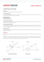
HARMONIC REDUCERS TECHNICAL INFORMATION TERMS AND DEFINITIONS RATED TORQUE Rated torque indicates allowable continuous load torque at rated input speed. LIMIT FOR AVERAGE TORQUE In cases where load torque and input speed vary, it is necessary to calculate an average value of load torque. The table indicates the limit for average torque. The average torque calculated must not exceed this limit. MAXIMUM AVERAGE INPUT SPEED MAXIMUM INPUT SPEED Do not exceed the allowable rating. LIMIT FOR REPEATED PEAK TORQUE During acceleration and deceleration the Harmonic Reducer gear experiences a peak...
Open the catalog to page 4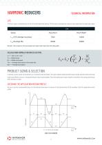
TECHNICAL INFORMATION HARMONIC REDUCERSLIFE The life of a gear is determined by the life of the wave generator bearing. The life may be calculated by using the input speed and the output load torque. Remark: Life is based on the input speed and output load torque from the rating table. CALCULATION FORMULA FOR RATED LIFETIME Tr-Rated torque Nr--Rated input speed Tav-Average load torque on the output side Nav-Average input speed PRODUCT SIZING & SELECTION In general, a servo system rarely operates at a continuous load and speed. The input rotational speed and load torque change and also...
Open the catalog to page 5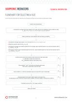
HARMONIC REDUCERS TECHNICAL INFORMATION FLOWCHART FOR SELECTING A SIZE Use the flowchart shown below for selecting a size. Operating conditions must not exceed the performance ratings. Confirm load characteristics 1.Calculate the average load torque applied on the output side from the application motion profile:Tav (Nm). Tav=((n1*t1* | T1 | 3+n2*t2* | T2 | 3+n3*t3*T3)/(n1*t1+n2*t2+n3*t3))^(1/3) Make a preliminary model selection with the following conditions. 1.Calculate the average output speed: no av (r/min)noav=(n1*t1+n2 *t2 +n3 *t3 )/(t1 +t2 +t3 ) 2.Obtain the reduction ratio...
Open the catalog to page 6
HARMONIC REDUCERS instruction for use Be sure to use the recommended values for the housing shown below to achieve the best performance of the assembly. Housing assembly surface
Open the catalog to page 7
HARMONIC REDUCERS INSTALLATION DESCRIPTION RSU SERIES INSTALLATION EXAMPLE CS FOR FIXATION, FS FOR OUTPUT Input the fixed flange Fill the interior with grease Pay attention to interference here, the detailed size is shown in the picture Output terminal Make sure to be sealed Wave generator Make sure to be sealed Motor adaptor flange RSH SERIES INSTALLATION EXAMPLE CS FOR FIXATION, FS FOR OUTPUT Input the fixed flange Motor adaptor flange Fill interior with grease Wave generator Make sure to be sealed Pay attention to interference here, the detailed size is shown in the picture Make sure to...
Open the catalog to page 8
HARMONIC REDUCERS INSTALLATION DESCRIPTION RSH SERIES INSTALLATION EXAMPLE 2 When the Flex Spline (FS) is fixed and the Circular Spline (CS) is the output, the reduction ratio is the indicated reduction ratio +1. Motor adaptor flange Fill grease here Motor with flange Wave generator 1. Fix the motor to the flange and fix the combination of the FS, CS and the crossed roller bearing to the flange. 2. lnstall the wave generator on the motor shaft. Notes: a. Do not use excessive force while assembling. The wave Generator can be installed by spinning it counter to the Flex Spline. b. Do not tilt...
Open the catalog to page 9
HARMONIC REDUCERS INSTALLATION DESCRIPTION COMMON CONNECTION METHODS OF WAVE GENERATORS Wave generator Key Plain washer Input shaft 1. The input shaft has a shoulder that can be directly attached to the wave generator. Screw Wave generator Key Plain washer Input shaft 2. The input shaft is connected to the wave generator after adding the spacer ring. The input shaft has a shoulder with a length too long, and a spacer (the parallelism of the two sides of the spacer ring shall be within 0.01mm) can be applied to the shaft and then the shaft can be fixed to the wave generator. Spacer ring Wave...
Open the catalog to page 10
HARMONIC REDUCERS INSTALLATION DESCRIPTION Correct installation Wrong installation 1. The harmonic reducer shall be installed in a clean environment, and no foreign matter is allowed to enter the inside of the reducer during installation to avoid damage to the reducer during use. 2. Make sure that the gear face and flexible bearing parts of the reducer are always lubricated adequately. It is not recommended to always use the gears with the teeth facing up, as this impairs the lubricating effect. 3. Do not change the product part combination. As the complete set guarantees their performance,...
Open the catalog to page 11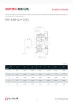
MECHANICAL PRECISION HARMONIC REDUCERS All products are subject to strict factory inspection. In order to ensure the accuracy of the whole machine, the following requirements are made to the mechanical precision of the harmonic reducer.
Open the catalog to page 12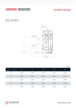
HARMONIC REDUCERS MECHANICAL PRECISION RCU-R SERIES Unit:mm INFRANOR WWW.INFRANOR.COM
Open the catalog to page 13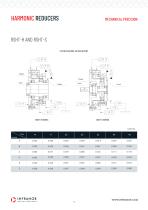
HARMONIC REDUCERS MECHANICAL PRECISION RSHT-H AND RSHT-S FS FOR FIXATION, CS FOR OUTPUT RSHT-H SERIES
Open the catalog to page 14All INFRANOR catalogs and technical brochures
-
CybIO
6 Pages
-
Xtrafors WASHDOWN
2 Pages
-
Xtrafors FP PRIME
2 Pages
-
Xtrafors MSA
2 Pages
-
Xtrafors EX
2 Pages
-
Xtrafors BR
2 Pages
-
Xtrafors BL
2 Pages
-
Movinor® T
4 Pages
-
XtracontrolDC2
4 Pages
-
VisiTouch CNC
2 Pages
-
VisiTouch CNC
6 Pages
-
Movinor® T AC Servomotors
4 Pages


