- Catalogs
- Infranor Group
- VDSetup_Manual_en_1.6


- Products
- Catalogs
- News & Trends
- Exhibitions
VDSetup_Manual_en_1.6
1 /69Pages

VDSetup_Manual_en_1.6
1 /69Pages
Catalog excerpts

VISUAL DRIVE SETUP Parameterization software for INFRANOR drives User manual Visual Drive Setup
Open the catalog to page 1
Visual Drive Setup ! VISUAL DRIVE SETUP is a parameterization software for INFRANOR servo drives. It shall be used only by skilled operators, according to the EN 60204-1 standard. During the drive parameterization, the operator has to read carefully the messages displayed by the software as the execution of some procedures requires special safety measures. The commissioning of INFRANOR drives also requires to follow the instructions contained in the pertaining manuals. INFRANOR does not assume any responsibility for any physical or material damage due to improper use of the VISUAL DRIVE SETUP...
Open the catalog to page 2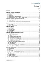
Content PAGE
Open the catalog to page 3
Visual Drive Setup
Open the catalog to page 4
Chapter 1 – General description 1.1 - INTRODUCTION The VISUAL DRIVE SETUP (VDSetup) software is designed for the parameterization of the INFRANOR "B" and "C" series drives from a PC and via an RS232 serial link. Further, this software allows the user to run a motor in speed control or to start a motion sequence (positioners) for checking the correct parameterization. 1.2 - VALIDITY The present issue of this manual is valid as from the pertaining version 4.0 of the Visual Drive Setup software. The auto-phasing procedure allows the automatic calculation of the motor parameters and the resolver...
Open the catalog to page 5
Visual Drive Setup Chapter 2 – Installation of the software 2.1 - MINIMUM CONFIGURATION The use of the Visual Drive Setup software requires the minimum PC configuration described below: - Pentium II processor, 32 MB RAM, screen with 256 colours and 800x600 resolution keyboard + mouse Windows95© or WindowsNT4© operating system 8 MB available on the hard disk. RS232 cable or USB/RS232 adapter cable. 2.2 - INSTALLATION From disks Insert disk n° 1 and double-click on file "setup.exe" of this disk. Follow the instructions until the complete installation of the software. From a CD-Rom Insert the CD...
Open the catalog to page 6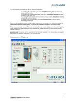
The communication parameters can get the following modifications: - For modifying the port number, go to menu Setup/Select Com_Port and select a port among COM1 to COM8. For modifying the communication speed, go to menu Setup/Select Baudrate and select a speed among the listed ones. For entering the serial address of the connected drive, go to menu Setup/Select Address, and select an address in the list. For setting up the communication, go to menu Setup/Connect or click on the icon representing a telephone. Every time the hardware connection with an amplifier is performed, the number of the...
Open the catalog to page 7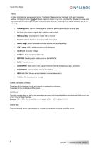
Visual Drive Setup Status: A status indicator may group several errors. The detail of these errors is displayed in the error messages window. Clicking on button Reset will delete the errors stored in the drive, provided that these errors have been cancelled before. According to the type of the connected drive, the meaning of the status indicators will be the following: Following error: Dynamic following error (speed or position, according to the drive type). I2t: Motor rms current is higher than the drive rated current. RDC/Counting: Counting error (motor with a resolver) Position sensor: Resolver...
Open the catalog to page 8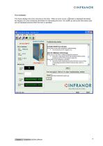
Error messages: This frame displays the errors occuring on the drive. When an error occurs, a ? button is displayed that allows the display of an area containing information for eliminating this error. This button as well as the information area are not displayed anymore when the error is cancelled. Chapter 2 – Installation of the software
Open the catalog to page 9
Visual Drive Setup The software makes possible, for the operator: - to know the amplifier type and rating (automatic detection when connecting), - to display the errors, the status of the control signals and of the inputs/outputs, - to programme the sensor type (encoder or resolver) on the latest generation CD1 amplifiers, - to start the auto-phasing procedure, - to start the auto-tuning procedure, - to start the acquisition and cogging torque compensation procedures, - to manually adjust the servo loop gains, - to adjust the various parameters (motor, limitations, application, ...), - to display...
Open the catalog to page 10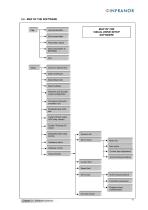
MAP OF THE VISUAL DRIVE SETUP SOFTWARE Load parameters Save parameters Parameters report Store parameters to EEPROM Connect / Disconnect Select COM port Select Baud rate Select address Resolver and encoder inputs configuration Command connector emulation bus Disable/Enable CAN bus Undervolt fault opens AOK relay contact Enable "Phasing Ok" output Disable/Enable brake Control General info Servo motor Hardware option Motor list New motor Software control Current loop adjustment Setup Window Auto-phasing procedure Current limit Speed limit Servo loop Auto-tuning procedure Controller parameters Cogging...
Open the catalog to page 11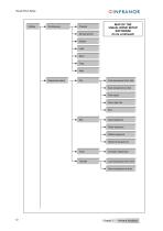
Visual Drive Setup Channel Sample period MAP OF THE VISUAL DRIVE SETUP SOFTWARE (to be continued) Display Load Save Copy Help Sequences setup Load sequences from disk Save sequences to disk Print report Save report as .. Exit Copy sequence Paste sequence Delete sequence Delete All sequences Compare sequences Load sequences from drive Save sequences to drive Chapter 3 – Software functions
Open the catalog to page 12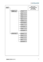
MAP OF THE VISUAL DRIVE SETUP SOFTWARE (to be contined) Positioner application setup Profile Safety Modulo Brake Positioner Manual movement Profibus Inputs-Outputs Scaling Second sensor Application setup Application CAN bus Scaling Safety Second sensor Chapter 3 – Software functions
Open the catalog to page 13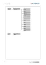
Visual Drive Setup Offline Mode About Visual Drive Setup Chapter 3 – Software functions
Open the catalog to page 14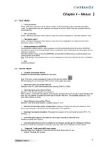
Chapter 4 – Menus 4.1 - "FILE" MENU Ö Load parameters Opens a Windows dialog box which allows to select, in the directories, a file containing parameters (*.par). The parameters read are displayed and loaded in the drive RAM if they are compliant with the connected drive. Ö Save parameters Opens a Windows dialog box which allows to save the current parameters in a file with extension ".par" Ö Parameters report Opens a Windows dialog box which allows to save the drive configuration and status as well as the parameter values in a text file. Ö Store parameters to EEPROM The parameters defined during...
Open the catalog to page 15All Infranor Group catalogs and technical brochures
 XtrapulsPac_EN
4 Pages
 XtrapulsGemTemplates_e_1.4
21 Pages
 XtrapulsGem_User_Manual_v1.2.0.64
199 Pages
 XtrapulsGem_Inst_e_2.1
42 Pages
 XtrapulsGem_Inst_e_2.0
42 Pages
 STO_declaration_Gem
2 Pages
 SMTBSi-2Tz_en_2.1
43 Pages
![SMT100D_e_1.01[1]](https://img.directindustry.com/pdf/repository_di/4620720/smt100d-e-101-1-1141223_1mg.jpg) SMT100D_e_1.01[1]
SMT100D_e_1.01[1]40 Pages
 smt-100
32 Pages
 PacSimBox_e
1 Page
 PacSimBox_d_1
1 Page
 Pac-SF01_flyer_en_18.02
4 Pages
 Pac_User_1.2.1.218
253 Pages
 Pac_Templates_en_1.9
27 Pages
 Pac_STO_Installation_en_2.2
13 Pages
 Pac_SF01_operating_en_1.6
63 Pages
 Pac_SF01_EN
4 Pages
 Pac_Installation_en_2.23
82 Pages
 Pac_GDPS_CEconformity
1 Page
 Pac_flyer_en_17.12
4 Pages
 Pac_EC_conformity_25.04
1 Page
 Option_CT_EMF
6 Pages
 MOVINOR_LH055_LH086_LH097_LH142
23 Pages
 ma_series
6 Pages
 GemSafeTorqueOff_en_1.1
12 Pages
 GemProgramming_e_1.1
47 Pages
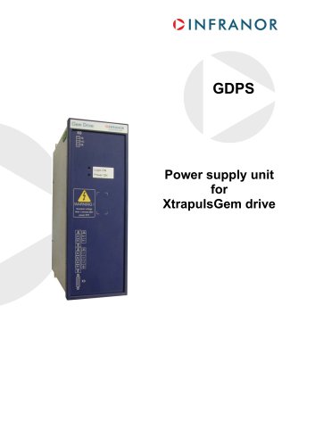 GDPS_old_version_1.1_1
11 Pages
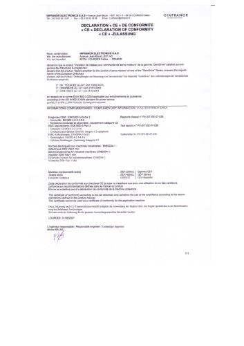 CE_conformity_Gem
1 Page
 CD1pm_e_1.2(old)
18 Pages
 CD1pInst_e_7.2(old)
35 Pages
 CD1kInst_e_4.1(old)
40 Pages
 CD1k_CANopenProtocol_e_1.3(old)
86 Pages
 CD1a_e_7.1(old)
45 Pages
 Catalogue gamme SMT-BD1
11 Pages
 BM20A(F)v3_0
20 Pages
 BM20A(D)v3_0
20 Pages
 BF400(GB)v2_2
21 Pages
 BF400(D)v2_2
21 Pages
 BF230(GB)v2_0
23 Pages
 BF230(F)v2_0
23 Pages
 BD2m_e_2.2
69 Pages
 BD2m(GB)2.0
70 Pages
 BD2_e_3.2
53 Pages
 BD2(GB)3.1
53 Pages
 BD2(D)3.1
54 Pages
 Movinor_LH_e
4 Pages
 ma_series
6 Pages
 BD1t(GB)3.1
81 Pages
 BD1t(F)3.0
85 Pages
 BD1pInst(GB)3.0
25 Pages
 BD1pInst(F)3.0
23 Pages
 BD1pInst(D)3.0
24 Pages
 BD1pCD1pUse_e_2.4
57 Pages
 BD1m(GB)5.0
58 Pages
 BD1m(F)5.0
57 Pages
 BD1m(D)v3_3
64 Pages
 BD1k(GB)2.1
35 Pages
 BD1k(F)2.1
36 Pages
 BD1j(GB)v2_41
19 Pages
 BD1j(F)v2_4
21 Pages
 BD1i(GB)v2_21
23 Pages
 BD1i(F)v2_2
27 Pages
 BD1h(F)3.0
65 Pages
 BD1h(D)3.0
59 Pages
 BD1g(GB)v3_0
28 Pages
 BD1g(F)v3_0
28 Pages
 BD1f(GB)v2_01
18 Pages
 BD1f(F)v2_01
17 Pages
 BD1e(F)v2_01
22 Pages
 BD1d(GB)v2_01
25 Pages
 BD1d(F)v2_01
25 Pages
 BD1c(GB)v2_01
19 Pages
 BD1c(F)v2_01
19 Pages
 BD1a400(GB)v2_3
43 Pages
 BD1a400(F)v2_3
44 Pages
 BD1a400(D)v2_3
45 Pages
 BD1(GB)7.1_noPW
45 Pages
 BD1(GB)7.1
45 Pages
 BD1(F)7.1_noPW
47 Pages
 BD1(F)7.1
47 Pages
 BD1(D)7.1
45 Pages
 BD1 Katalog
11 Pages
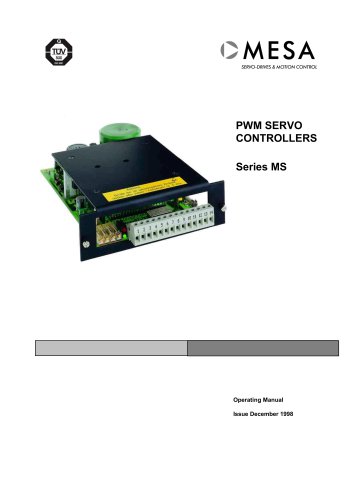 08ma_ms_e_01700
20 Pages
 Easy_User_5.0.1.60.2
190 Pages
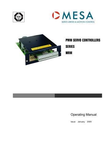 08ma_mrm_em_01575
20 Pages
 01ma_smv_e_01953
40 Pages
 PacHP-SF_Flyer_en_23.06
4 Pages
 IRD_User_Manual_en_1.2.XX.54.rev_b
216 Pages
 PacHP_User_en_1.2.8.100.b
280 Pages
 PacHP_TÜV_certificate_25.07
2 Pages
 PacHP_SF02_operating_en_1.6
103 Pages
 PacHP_SF01_operating_en_2.0
63 Pages
 PacHP_Installation_en_2.9
91 Pages
 PacHP_Series_Brochure
8 Pages
 PacHP_Flyer_us_20.10
4 Pages
 IRD_Installation_en_1.5
42 Pages
 IRD_EC_Conformity_25.03
1 Page
 GDPS_Installation_en_4.4
18 Pages
 EtherCAT Interface_en_1.3
20 Pages
 GDPS_EC_conformity_24.07
1 Page
 Easy_STO_en_1.4
14 Pages
 Easy_EC_Conformity_24_10
1 Page
 Easy_DB_STO_en_1.2
14 Pages
 Easy_DB_Installation_en_1.4
36 Pages
 CD1pmUser_en_4.2
55 Pages
 CD1pmInst_en_8.15
40 Pages
 CD1k_CANopenProtocol_en_2.10.1.1
108 Pages
 CD1pm_ProfibusProtocol_en_1.5
50 Pages
 CD1kUser_en_2.3
26 Pages
 CD1a_en_8.17
62 Pages
 CD1kInst_en_5.16
46 Pages
 CD1_STO_en_1.8
16 Pages
 CD1_STO_conformity_19.02
2 Pages
 CD1_flyer_en_14.09
4 Pages
 CD1_EC_conformity_24.05
1 Page
 Braking_Resistors_en_1.5
10 Pages
 AN_DC_bus_interfacing_en_1.3
5 Pages
 AN_CD1pm_SinCosTracks_e_1.0
7 Pages
 AN_CD1pm_AbsoluteEncoder_en_2.0
10 Pages
 AN_CD1ak_SinCosTracks_e_1.0
7 Pages
 AN_CD1ak_AbsoluteEncoder_en_2.0
10 Pages
 XtracontrolDC2_EN
4 Pages
 Flyer_VisiTouchCNC_EN_V1.1-1
2 Pages
 XtraforsWashdown_EN-2024
2 Pages
 DataSheet_CybIO_CNC_V1.0
6 Pages
 XtraforsPrime_EN-2024
2 Pages
 XtraforsMSS_EN
4 Pages
 XtraforsMSA_EN_2024
2 Pages
 XtraforsEx_EN-2024
2 Pages
 XtraforsBR_EN-2024
2 Pages
 XtraforsBL_EN-2024
2 Pages
 XtraforsBC-ed01-vs3
4 Pages
 Manual_XtraforsPrime
46 Pages
 Drawing_1
1 Page
 Datasheet_MSS
5 Pages
 Datasheet_2
2 Pages
 Datasheet_1
4 Pages
 BLSBLT_series
2 Pages
 BL220221
2 Pages
 BL270
BL2702 Pages
 BL190
BL1902 Pages
 bl100_series
6 Pages
 bl40_series
6 Pages
 BL30
BL302 Pages
 2019-01_XtraforsFP-DSL_FR
4 Pages
 Movinor_T_EN
4 Pages
 Movinor_N_EN
4 Pages
 Movinor_Low_Voltage_EN
4 Pages
 Manual Movinor T 03-2026
46 Pages
 Manual Movinor N 03-2026
63 Pages
 XtrapulsEasy™ AC servo-drive
4 Pages
 XtrapulsCD1 AC servo-drives
4 Pages
 CybIO
CybIO6 Pages
 AC SERVOMOTORS
2 Pages
 Movinor® N AC Servomotors
4 Pages