
- Catalogs
- Infranor Group
- SMTBSi-2Tz_en_2.1


SMTBSi-2Tz_en_2.1
1 /43Pages

SMTBSi-2Tz_en_2.1
1 /43Pages
Catalog excerpts
Brushless servo controllers Transmitter Resolver Type
Open the catalog to page 1
This is a general manual describing a series of servo amplifiers having output capability suitable for driving AC brushless sinusoidal servo motors. This manual may be used in conjunction with appropriate and referenced drawings pertaining to the various specific models. Maintenance procedures should be attempted only by highly skilled technicians (EN 60204.1 standard) using proper test equipment. The conformity with the standards and the "CE" approval are only valid if the items are installed according to the recommendations of the racks and amplifiers manuals. Any contact with electrical parts,...
Open the catalog to page 2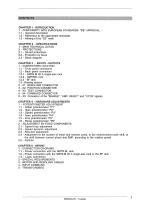
1 - CONFORMITY WITH EUROPEAN STANDARDS: "CE" APPROVAL 1.2 - Reference to the appropriate standards 1 - MAIN TECHNICAL DATAS CHAPTER 3 - INPUTS - OUTPUTS 1.1 - Front panel connectors 1.2 - Back panel connectors 1.2.1 - SMTB.M 20 A single-axis rack 3 - X2 POSITION CONNECTOR 4-X3 TEST CONNECTOR 6 - X5 Connector of the "ENABLE", "AMP. READY" and "I DYN" signals CHAPTER 4 - HARDWARE ADJUSTMENTS 2 - ADJUSTMENT BY FIXED COMPONENTS 2.1 - Speed loop adjustment 2.2 - Speed dynamic adjustment 2.4 - Adjustment to the number of motor and resolver poles, to the motor/resolver pole shift, to the shift between...
Open the catalog to page 3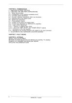
1 - AMPLIFIER OUTSIDE THE RACK 2 - CHECKING THE AMPLIFIER CONFIGURATION 2.1 - Motor thermal probe 2.2 - Configuration of the resolver processing circuit 2.3 - Converter speed adjustment 2.4 - Encoder resolution adjustment within one revolution 2.5 - Electrical shift of the marker pulse 2.6 - Speed loop adjustment 2.8 - Location of the power and supply fuses 2.9 - Current loop adjustment on SMTB.Si-2Tz amplifiers 2.10 - Logic control adjustment 2.10.1 - Positive or negative logic inputs 2.10.2 - Use of the "AMP. READY" and "POWER READY" outputs 2.11 - Connection of the first amplifier 2.12 - Reversal...
Open the catalog to page 4
The SMTB.Si amplifiers have their own DC/DC converter to provide appropriate logic voltage to the modules. This power supply uses, as a source, an auxiliary supply which is particularly necessary when the position output information needs to be saved, independently of the power supply. Each module is packaged as a 6 U "double Eurocard": • one power board with IGBT transistors • one analogue logic board with resolver sensor interface. The SMTB.Si amplifier directly controls the motor torque and speed by means of the information provided by a transmitter resolver sensor. The adjustment to the number...
Open the catalog to page 5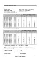
Operating voltage Auxiliary supply voltage Motor phase-phase output voltage Output currents for a Pulse mode cycle Max. authorised rated current (Arms) ___of the amplifier__ Output currents for a Constant current cycle AMPLIFIER TYPE Max. authorized continuous current (Arms) of the amplifier ____ * Maximum ambient temperature = + 40° C, fan 1 = 56 I/s, fan 2 = 90 I/s. Note: The SMTB.SI-2Tz amplifier types are equipped with an additional heatsink in order to improve the heat dissipation and increase their rated current. The width of these amplifier types is then 18 TE instead of 12 TE. Minimum...
Open the catalog to page 6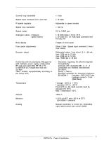
Current loop bandwidth Speed input command CV1 and CV2 Speed loop bandwidth Speed range Analogue output: I measure speed monitor Error display Front panel adjustments Encoder output Conformity with the standards: CE approval with multiaxis power supply configuration BF rack and mains filter BF 35 or 70, or SMTB.M 20 A single-axis rack and 35 filter "360°" shields; equipotentiality according to the wiring rules. Adjustable to speed module ±10 Volts for ± 10 Volts input command and P3 fully CW Offset / Gain / Speed input command / Imax / Irms / Ramp Differential output, "Line driver" 5 V / 20 mA...
Open the catalog to page 7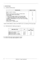
2 - PROTECTIONS 2.1 - STORED PROTECTIONS FI: Control of the power supply average DC current. F2: Control of the logic supply average DC current.
Open the catalog to page 8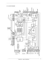
Default reset
Open the catalog to page 9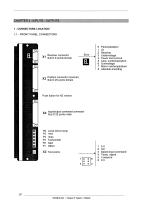
1 - CONNECTORS LOCATION 1.1 - FRONT PANEL CONNECTORS Input/output command connector A^ Sub D 25 points male P6 Accel./decel ramp P5 irms P4 I max P3 Tachometer P2 Gain PI Offset SMTB.Si-2Tz • Chapter 3: Inputs - Outputs 3 Speed input command
Open the catalog to page 10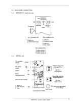
1.2 - BACK PANEL CONNECTORS 1.2.1 - SMTB.M 20 A single-axis rack three-phase input Diode bridge of the AUX. SUPPLY 1R siT| Diode bridge of the POWER SUPPLY Reference grounding on the flange SMTB.Si-2Tz • Chapter 3: Inputs - Outputs
Open the catalog to page 11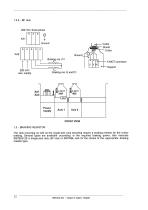
The rack mounting as well as the single-axis rack mounting require a braking resistor for the motor braking. Several types are available according to the required braking power. See manuals SMTB.M 20 A single-axis rack, BF rack or SMTRBL rack for the choice of the appropriate braking resistor type. SMTB.Si-2Tz • Chapter 3: Inputs - Outputs
Open the catalog to page 12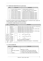
2 - XI RESOLVER CONNECTOR Sub D 9 points female SMTB.Si-2Tz • Chapter 3: Inputs - Outputs
Open the catalog to page 13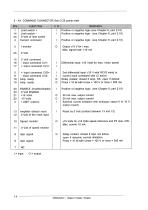
5 - X4 COMMAND CONNECTOR Sub D 25 points male Limit switch - 0 Volt of limit switch Current command - Input command CV1-+ Input command CV1 + - Input command CV2-Amp. ready ENABLE (enable/disable) 0 Volt ENABLE +15 Volts Amplifier default reset 0 Volt of the reset input Speed monitor 0 Volt of speed monitor Idyn signal Idyn signal Positive or negative logic (see Chapter 6, part 2.10) Positive or negative logic (see Chapter 6, part 2.10) Positive or negative logic (see Chapter 6, part 2.10) Differential input: ±10 Volts for max. motor speed 2nd differential input ±10 V with RCV2 wired or current...
Open the catalog to page 14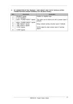
6 - X5 CONNECTOR OF THE "ENABLE", "AMP. READY" AND "I DYN" SIGNALS (8 PINS CONNECTOR WITH SCREW TERMINALS ON THE BACK PANEL) SMTB.Si-2Tz • Chapter 3: Inputs - Outputs
Open the catalog to page 15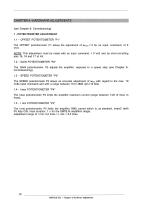
The OFFSET potentiometer PI allows the adjustment of wmotor = 0 for an input command of 0 Volt. NOTE: This adjustment must be made with an input command = 0 Volt and by short-circuiting pins 15, 16 and 17 of X4. The GAIN potentiometer P2 adjusts the amplifier response to a speed step (see Chapter 6: Commissioning). The SPEED potentiometer P3 allows an accurate adjustment of wmax with regard to the max. 10 Volts input command and with a range between 10 to 4800 rpm (12 bits). The Imax potentiometer P4 limits the amplifier maximum current (range between 1/20 of Imax to Imax). The I rms potentiometer...
Open the catalog to page 16All Infranor Group catalogs and technical brochures
 XtrapulsPac_EN
4 Pages
 PacSimBox_d_1
1 Page
 Pac-SF01_flyer_en_18.02
4 Pages
 Pac_User_1.2.1.218
253 Pages
 Pac_Templates_en_1.9
27 Pages
 Pac_STO_Installation_en_2.2
13 Pages
 Pac_SF01_operating_en_1.6
63 Pages
 Pac_SF01_EN
4 Pages
 Pac_Installation_en_2.23
82 Pages
 Pac_flyer_en_17.12
4 Pages
 Option_CT_EMF
6 Pages
 MOVINOR_LH055_LH086_LH097_LH142
23 Pages
 ma_series
6 Pages
 GemSafeTorqueOff_en_1.1
12 Pages
 CD1pm_e_1.2(old)
18 Pages
 CD1pInst_e_7.2(old)
35 Pages
 CD1kInst_e_4.1(old)
40 Pages
 CD1k_CANopenProtocol_e_1.3(old)
86 Pages
 CD1a_e_7.1(old)
45 Pages
 Catalogue gamme SMT-BD1
11 Pages
 BM20A(F)v3_0
20 Pages
 BM20A(D)v3_0
20 Pages
 BF400(GB)v2_2
21 Pages
 BF400(D)v2_2
21 Pages
 BF230(GB)v2_0
23 Pages
 BF230(F)v2_0
23 Pages
 BD2m_e_2.2
69 Pages
 BD2m(GB)2.0
70 Pages
 BD2_e_3.2
53 Pages
 BD2(GB)3.1
53 Pages
 BD2(D)3.1
54 Pages
 Movinor_LH_e
4 Pages
 ma_series
6 Pages
 BD1t(GB)3.1
81 Pages
 BD1t(F)3.0
85 Pages
 BD1pInst(GB)3.0
25 Pages
 BD1pInst(F)3.0
23 Pages
 BD1pInst(D)3.0
24 Pages
 BD1pCD1pUse_e_2.4
57 Pages
 BD1m(GB)5.0
58 Pages
 BD1m(F)5.0
57 Pages
 BD1m(D)v3_3
64 Pages
 BD1k(GB)2.1
35 Pages
 BD1k(F)2.1
36 Pages
 BD1j(GB)v2_41
19 Pages
 BD1j(F)v2_4
21 Pages
 BD1i(GB)v2_21
23 Pages
 BD1i(F)v2_2
27 Pages
 BD1h(F)3.0
65 Pages
 BD1h(D)3.0
59 Pages
 BD1g(GB)v3_0
28 Pages
 BD1g(F)v3_0
28 Pages
 BD1a400(GB)v2_3
43 Pages
 BD1a400(F)v2_3
44 Pages
 BD1a400(D)v2_3
45 Pages
 BD1(GB)7.1_noPW
45 Pages
 BD1(GB)7.1
45 Pages
 BD1(F)7.1_noPW
47 Pages
 BD1(F)7.1
47 Pages
 BD1(D)7.1
45 Pages
 BD1 Katalog
11 Pages
 Easy_User_5.0.1.60.2
190 Pages
 01ma_smv_e_01953
40 Pages
 PacHP-SF_Flyer_en_23.06
4 Pages
 IRD_User_Manual_en_1.2.XX.54.rev_b
216 Pages
 PacHP_User_en_1.2.8.100.b
280 Pages
 PacHP_SF02_operating_en_1.6
103 Pages
 PacHP_SF01_operating_en_2.0
63 Pages
 PacHP_Installation_en_2.9
91 Pages
 PacHP_Series_Brochure
8 Pages
 PacHP_Flyer_us_20.10
4 Pages
 IRD_Installation_en_1.5
42 Pages
 Easy_STO_en_1.4
14 Pages
 Easy_DB_STO_en_1.2
14 Pages
 Easy_DB_Installation_en_1.4
36 Pages
 CD1pmUser_en_4.2
55 Pages
 CD1pmInst_en_8.15
40 Pages
 CD1k_CANopenProtocol_en_2.10.1.1
108 Pages
 CD1pm_ProfibusProtocol_en_1.5
50 Pages
 CD1kUser_en_2.3
26 Pages
 CD1a_en_8.17
62 Pages
 CD1kInst_en_5.16
46 Pages
 CD1_STO_en_1.8
16 Pages
 CD1_flyer_en_14.09
4 Pages
 Braking_Resistors_en_1.5
10 Pages
 XtracontrolDC2_EN
4 Pages
 Flyer_VisiTouchCNC_EN_V1.1-1
2 Pages
 XtraforsWashdown_EN-2024
2 Pages
 DataSheet_CybIO_CNC_V1.0
6 Pages
 XtraforsPrime_EN-2024
2 Pages
 XtraforsMSS_EN
4 Pages
 XtraforsMSA_EN_2024
2 Pages
 XtraforsEx_EN-2024
2 Pages
 XtraforsBR_EN-2024
2 Pages
 XtraforsBL_EN-2024
2 Pages
 XtraforsBC-ed01-vs3
4 Pages
 Manual_XtraforsPrime
46 Pages
 Drawing_1
1 Page
 Datasheet_MSS
5 Pages
 Datasheet_2
2 Pages
 Datasheet_1
4 Pages
 BLSBLT_series
2 Pages
 BL220221
2 Pages
 BL270
BL2702 Pages
 BL190
BL1902 Pages
 bl100_series
6 Pages
 bl40_series
6 Pages
 BL30
BL302 Pages
 2019-01_XtraforsFP-DSL_FR
4 Pages
 Movinor_T_EN
4 Pages
 Movinor_N_EN
4 Pages
 Movinor_Low_Voltage_EN
4 Pages
 Manual Movinor T 03-2026
46 Pages
 Manual Movinor N 03-2026
63 Pages
 XtrapulsEasy™ AC servo-drive
4 Pages
 XtrapulsCD1 AC servo-drives
4 Pages
 CybIO
CybIO6 Pages
 AC SERVOMOTORS
2 Pages
 Movinor® N AC Servomotors
4 Pages






Archived catalogs
 AN_CD1ak_AbsoluteEncoder_en_2.0
10 Pages
 AN_CD1ak_SinCosTracks_e_1.0
7 Pages
 AN_CD1pm_AbsoluteEncoder_en_2.0
10 Pages
 AN_CD1pm_SinCosTracks_e_1.0
7 Pages
 AN_DC_bus_interfacing_en_1.3
5 Pages
 CD1_EC_conformity_24.05
1 Page
 CD1_STO_conformity_19.02
2 Pages
 EtherCAT Interface_en_1.3
20 Pages
 Easy_EC_Conformity_24_10
1 Page
 GDPS_EC_conformity_24.07
1 Page
 IRD_EC_Conformity_25.03
1 Page
 PacHP_TÜV_certificate_25.07
2 Pages
 BD1c(F)v2_01
19 Pages
 BD1c(GB)v2_01
19 Pages
 BD1d(F)v2_01
25 Pages
 BD1d(GB)v2_01
25 Pages
 BD1e(F)v2_01
22 Pages
 BD1f(F)v2_01
17 Pages
 BD1f(GB)v2_01
18 Pages
 Pac_EC_conformity_25.04
1 Page




















