- Catalogs
- Infranor Group
- SMT100D_e_1.01[1]


SMT100D_e_1.01[1]
1 /40Pages
![SMT100D_e_1.01[1]](https://img.directindustry.com/pdf/repository_di/4620720/smt100d-e-101-1-1141223_1mg.jpg)
SMT100D_e_1.01[1]
1 /40Pages
Catalog excerpts
![SMT100D_e_1.01[1]-1](https://img.directindustry.com/pdf/repository_di/4620720/smt100d-e-101-1-1141223_1m.jpg)
SERVO DRIVES & MOTION CONTROL SMT-100-I-D amplifier MP/DR 100-A power supply unit 1-4-6 axes CA-x Rack
Open the catalog to page 1![SMT100D_e_1.01[1]-3](https://img.directindustry.com/pdf/repository_di/4620720/smt100d-e-101-1-1141223_3m.jpg)
This is a general manual describing a series modules made of one power supply unit and one or several digital servo amplifiers having output capability suitable for driving DC servo motors. This manual may be used in conjunction with appropriate and referenced drawings pertaining to the various specific models. Maintenance procedures should be attempted only by highly skilled technicians (EN 60 2 0 4 . 1 standard) using proper test equipment. The conformity with the standards and the "CE" approval are only valid if the items are installed according to the recommendations of the racks and amplifiers...
Open the catalog to page 3![SMT100D_e_1.01[1]-7](https://img.directindustry.com/pdf/repository_di/4620720/smt100d-e-101-1-1141223_7m.jpg)
The 1,4 and 6 axes equipped INFRANOR rack are made of: - one MP/DR100A power supply unit, - one backplane receiving the whole wiring. The various modules are mechanically fastened on the rack, on a support plate by means of knurled screws that increase the heat dissipation. The whole unit has been certified with regard to its conformity with the EMC standards: - EN 55011, group 1, class A, regarding radioelectric disturbances, Chapter 1 - General description
Open the catalog to page 7![SMT100D_e_1.01[1]-8](https://img.directindustry.com/pdf/repository_di/4620720/smt100d-e-101-1-1141223_8m.jpg)
OINFRANOR Chapter 2 - MP/DR 100A power supply unit The function of the MP/DR100A a power supply unit is: • to provide the amplifier(s), from an alternative single-phase or three-phase source, with a rectified and filtered power voltage, • to generate, from an auxiliary 230 Vrms alternative single-phase input, the logic voltages required for the amplifier(s) supply, • to control the power voltage level during the motor braking phases (braking system). The power supply unit provides both power and logic supplies for up to 6 amplifiers. 1 - SPECIFICATIONS OF THE MP/DR100A MODULE - Aux. supply input...
Open the catalog to page 8![SMT100D_e_1.01[1]-9](https://img.directindustry.com/pdf/repository_di/4620720/smt100d-e-101-1-1141223_9m.jpg)
Filtering rectification Mains filter Power supply input Filtering rectification Cut-off supply Braking system Logic supplies 3 – CONNECTIONS 3.1 – X1 3 WAYS CONNECTOR : AUXILIARY SUPPLY INPUT ON MODULE FRONT PANEL Function Earth (ground) 230 Vrms +/- 10% input 230 Vrms +/- 10% input 3.2 – X20 BACKPLANE CONNECTOR : VOLTAGES DISPATCHING VIA THE BACKPLANE Chapter 2 - MP/DR100A power supply unit Inputs / outputs Alternative power input - phase 1 Alternative power input - phase 2 Alternative power input - phase 3 DC bus reference output: -UP DC bus output: +UP +15 V output 0 V output -15 V output...
Open the catalog to page 9![SMT100D_e_1.01[1]-10](https://img.directindustry.com/pdf/repository_di/4620720/smt100d-e-101-1-1141223_10m.jpg)
L1 : -15 V voltage available. L2 : +15 V voltage available. L3 : Power voltage available. Location of the protection fuses: See appendix - Chapter 7 "Part locations ". Chapter 2 - MP/DR 100A power supply unit
Open the catalog to page 10![SMT100D_e_1.01[1]-11](https://img.directindustry.com/pdf/repository_di/4620720/smt100d-e-101-1-1141223_11m.jpg)
The SMT100-I D amplifier module is a speed regulator for DC motors. This amplifier controls the speed of a DC motor at a certain input command voltage by means of a speed loop corresponding either to the motor voltage or to the encoder pulses counting. The SMT100-I D modules are digital amplifiers. All control parameters are programmable via a serial link and can be saved in an EEPROM. 1 - SPECIFICATIONS 1.1 - MAIN TECHNICAL DATA The SMT100-I-D amplifier is available with following current range: - Power supply voltage - Speed input command - Speed signal - Minimum load inductance - Modulation...
Open the catalog to page 11![SMT100D_e_1.01[1]-12](https://img.directindustry.com/pdf/repository_di/4620720/smt100d-e-101-1-1141223_12m.jpg)
- Front panel adjustment Speed offset 1.2 – BLOCK DIAGRAM +UP/-UP Encoder inputs connector X3 +5 V supply Motor voltage monitor Current monitor Analog input command sizing Speed loop Limit switches Encoder output AOK EEPROM Serial interface Current loop Protections processing PWM + power stage Faults AOK Power voltage reference « -Up » referenced to the rack. 1.3 – MODULE DIMENSIONS Chapter 3 – Amplier module SMT10
Open the catalog to page 12![SMT100D_e_1.01[1]-13](https://img.directindustry.com/pdf/repository_di/4620720/smt100d-e-101-1-1141223_13m.jpg)
1.4 - PROTECTIONS - Power stage overtemperature (fault memory storage) An overheating of the power stage (T > 90°C) is detected by a temperature sensor. The triggering of this protection disables the control of the power switches. - Overcurrent detection circuit (fault memory storage) This device disables the amplifier as soon as the current crossing the power stage exceeds the amplifier max. current (short-circuit at the motor phases). - Watching the power voltage Up Checking of the voltage available on the DC bus: 30 V < Up < 170 V : * power overvoltage for Up > 170 V +/-3 V (fault memory stored),...
Open the catalog to page 13![SMT100D_e_1.01[1]-14](https://img.directindustry.com/pdf/repository_di/4620720/smt100d-e-101-1-1141223_14m.jpg)
FAULTS CODES Power stage overtemperature Limitation at rated current Power overvoltage Note: To cancel the memory storage of any fault, just switch off the system. The ASCII instruction "RZ" allows to reset the faults. 2 – INPUTS – OUTPUTS The SMT100-I-D amplifier has 4 logic inputs as well as an amplifier fault warning output. 2.1 – ZERO INPUT COMMAND : cons. 0 When the "zero input command" contact opens, the amplifier sends a zero input command: immediate motor stopping (except for the offset variation) whatever the speed input command value. Positive logic input: 15 V < U < 24 V. The response...
Open the catalog to page 14![SMT100D_e_1.01[1]-15](https://img.directindustry.com/pdf/repository_di/4620720/smt100d-e-101-1-1141223_15m.jpg)
2.2 – LIMIT SWITCH INPUTS: FC+ and FCIf one of the limit switch contacts is activated during operation, the motor speed will be cancelled in the direction corresponding to the concerned limit switch (except for the offset variation). Negative logic inputs FC+ activated: The motor stops in CW direction (from motor front view). FC- activated: The motor stops in CCW direction (from motor shaft front view). The response time is about 500 µs. DIAGRAM OF THE LIMIT SWITCH INPUTS 2.3 – ENABLE INPUT The SMT100-I D amplifier is disabled when the ENABLE contact is open (free motor rotation). Negative logic...
Open the catalog to page 15![SMT100D_e_1.01[1]-16](https://img.directindustry.com/pdf/repository_di/4620720/smt100d-e-101-1-1141223_16m.jpg)
OINFRANOR 2.4 - LOGIC INPUTS CONNECTION Relay contact AOK opens if any amplifier fault occurs. Note: On the 4-6 axes rack, 2 outputs corresponding to the serial connection of the amplifiers AOK relay contacts allow to process the information "rack failure". This information processing is described in the wiring diagram of chapter 3, section 2.6. This connector allows: - the communication via serial link RS485 between amplifier(s) and ASCII terminal, - to connect the encoder signals with the NC in mode "Speed feedback by encoder signals". Chapter 3 - Amplier module SMT100-I-D
Open the catalog to page 16All Infranor Group catalogs and technical brochures
 XtrapulsPac_EN
4 Pages
 XtrapulsGemTemplates_e_1.4
21 Pages
 XtrapulsGem_User_Manual_v1.2.0.64
199 Pages
 XtrapulsGem_Inst_e_2.1
42 Pages
 XtrapulsGem_Inst_e_2.0
42 Pages
 STO_declaration_Gem
2 Pages
 SMTBSi-2Tz_en_2.1
43 Pages
 smt-100
32 Pages
 PacSimBox_e
1 Page
 PacSimBox_d_1
1 Page
 Pac-SF01_flyer_en_18.02
4 Pages
 Pac_User_1.2.1.218
253 Pages
 Pac_Templates_en_1.9
27 Pages
 Pac_STO_Installation_en_2.2
13 Pages
 Pac_SF01_operating_en_1.6
63 Pages
 Pac_SF01_EN
4 Pages
 Pac_Installation_en_2.23
82 Pages
 Pac_GDPS_CEconformity
1 Page
 Pac_flyer_en_17.12
4 Pages
 Pac_EC_conformity_25.04
1 Page
 Option_CT_EMF
6 Pages
 MOVINOR_LH055_LH086_LH097_LH142
23 Pages
 ma_series
6 Pages
 GemSafeTorqueOff_en_1.1
12 Pages
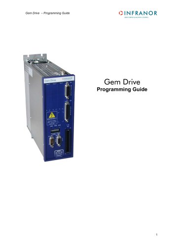 GemProgramming_e_1.1
47 Pages
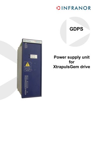 GDPS_old_version_1.1_1
11 Pages
 CE_conformity_Gem
1 Page
 CD1pm_e_1.2(old)
18 Pages
 CD1pInst_e_7.2(old)
35 Pages
 CD1kInst_e_4.1(old)
40 Pages
 CD1k_CANopenProtocol_e_1.3(old)
86 Pages
 CD1a_e_7.1(old)
45 Pages
 Catalogue gamme SMT-BD1
11 Pages
 BM20A(F)v3_0
20 Pages
 BM20A(D)v3_0
20 Pages
 BF400(GB)v2_2
21 Pages
 BF400(D)v2_2
21 Pages
 BF230(GB)v2_0
23 Pages
 BF230(F)v2_0
23 Pages
 BD2m_e_2.2
69 Pages
 BD2m(GB)2.0
70 Pages
 BD2_e_3.2
53 Pages
 BD2(GB)3.1
53 Pages
 BD2(D)3.1
54 Pages
 Movinor_LH_e
4 Pages
 ma_series
6 Pages
 BD1t(GB)3.1
81 Pages
 BD1t(F)3.0
85 Pages
 BD1pInst(GB)3.0
25 Pages
 BD1pInst(F)3.0
23 Pages
 BD1pInst(D)3.0
24 Pages
 BD1pCD1pUse_e_2.4
57 Pages
 BD1m(GB)5.0
58 Pages
 BD1m(F)5.0
57 Pages
 BD1m(D)v3_3
64 Pages
 BD1k(GB)2.1
35 Pages
 BD1k(F)2.1
36 Pages
 BD1j(GB)v2_41
19 Pages
 BD1j(F)v2_4
21 Pages
 BD1i(GB)v2_21
23 Pages
 BD1i(F)v2_2
27 Pages
 BD1h(F)3.0
65 Pages
 BD1h(D)3.0
59 Pages
 BD1g(GB)v3_0
28 Pages
 BD1g(F)v3_0
28 Pages
 BD1f(GB)v2_01
18 Pages
 BD1f(F)v2_01
17 Pages
 BD1e(F)v2_01
22 Pages
 BD1d(GB)v2_01
25 Pages
 BD1d(F)v2_01
25 Pages
 BD1c(GB)v2_01
19 Pages
 BD1c(F)v2_01
19 Pages
 BD1a400(GB)v2_3
43 Pages
 BD1a400(F)v2_3
44 Pages
 BD1a400(D)v2_3
45 Pages
 BD1(GB)7.1_noPW
45 Pages
 BD1(GB)7.1
45 Pages
 BD1(F)7.1_noPW
47 Pages
 BD1(F)7.1
47 Pages
 BD1(D)7.1
45 Pages
 BD1 Katalog
11 Pages
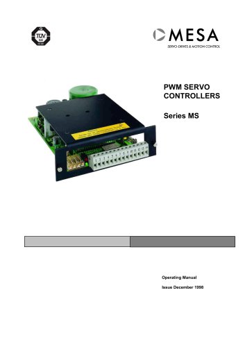 08ma_ms_e_01700
20 Pages
 Easy_User_5.0.1.60.2
190 Pages
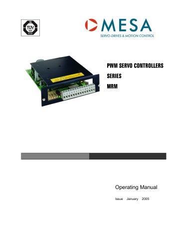 08ma_mrm_em_01575
20 Pages
 01ma_smv_e_01953
40 Pages
 PacHP-SF_Flyer_en_23.06
4 Pages
 IRD_User_Manual_en_1.2.XX.54.rev_b
216 Pages
 PacHP_User_en_1.2.8.100.b
280 Pages
 PacHP_TÜV_certificate_25.07
2 Pages
 PacHP_SF02_operating_en_1.6
103 Pages
 PacHP_SF01_operating_en_2.0
63 Pages
 PacHP_Installation_en_2.9
91 Pages
 PacHP_Series_Brochure
8 Pages
 PacHP_Flyer_us_20.10
4 Pages
 IRD_Installation_en_1.5
42 Pages
 IRD_EC_Conformity_25.03
1 Page
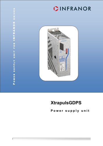 GDPS_Installation_en_4.4
18 Pages
 EtherCAT Interface_en_1.3
20 Pages
 GDPS_EC_conformity_24.07
1 Page
 Easy_STO_en_1.4
14 Pages
 Easy_EC_Conformity_24_10
1 Page
 Easy_DB_STO_en_1.2
14 Pages
 Easy_DB_Installation_en_1.4
36 Pages
 CD1pmUser_en_4.2
55 Pages
 CD1pmInst_en_8.15
40 Pages
 CD1k_CANopenProtocol_en_2.10.1.1
108 Pages
 CD1pm_ProfibusProtocol_en_1.5
50 Pages
 CD1kUser_en_2.3
26 Pages
 CD1a_en_8.17
62 Pages
 CD1kInst_en_5.16
46 Pages
 CD1_STO_en_1.8
16 Pages
 CD1_STO_conformity_19.02
2 Pages
 CD1_flyer_en_14.09
4 Pages
 CD1_EC_conformity_24.05
1 Page
 Braking_Resistors_en_1.5
10 Pages
 AN_DC_bus_interfacing_en_1.3
5 Pages
 AN_CD1pm_SinCosTracks_e_1.0
7 Pages
 AN_CD1pm_AbsoluteEncoder_en_2.0
10 Pages
 AN_CD1ak_SinCosTracks_e_1.0
7 Pages
 AN_CD1ak_AbsoluteEncoder_en_2.0
10 Pages
 XtracontrolDC2_EN
4 Pages
 Flyer_VisiTouchCNC_EN_V1.1-1
2 Pages
 XtraforsWashdown_EN-2024
2 Pages
 DataSheet_CybIO_CNC_V1.0
6 Pages
 XtraforsPrime_EN-2024
2 Pages
 XtraforsMSS_EN
4 Pages
 XtraforsMSA_EN_2024
2 Pages
 XtraforsEx_EN-2024
2 Pages
 XtraforsBR_EN-2024
2 Pages
 XtraforsBL_EN-2024
2 Pages
 XtraforsBC-ed01-vs3
4 Pages
 Manual_XtraforsPrime
46 Pages
 Drawing_1
1 Page
 Datasheet_MSS
5 Pages
 Datasheet_2
2 Pages
 Datasheet_1
4 Pages
 BLSBLT_series
2 Pages
 BL220221
2 Pages
 BL270
BL2702 Pages
 BL190
BL1902 Pages
 bl100_series
6 Pages
 bl40_series
6 Pages
 BL30
BL302 Pages
 2019-01_XtraforsFP-DSL_FR
4 Pages
 Movinor_T_EN
4 Pages
 Movinor_N_EN
4 Pages
 Movinor_Low_Voltage_EN
4 Pages
 Manual Movinor T 03-2026
46 Pages
 Manual Movinor N 03-2026
63 Pages
 XtrapulsEasy™ AC servo-drive
4 Pages
 XtrapulsCD1 AC servo-drives
4 Pages
 CybIO
CybIO6 Pages
 AC SERVOMOTORS
2 Pages
 Movinor® N AC Servomotors
4 Pages