- Catalogs
- Infranor Group
- smt-100


smt-100
1 /32Pages
smt-100
1 /32Pages
Catalog excerpts
OPERATING MANUAL SERIES SMT-100D DIGITAL BRUSHTYPE AMPLIFIER (Version 1.0) European version 1.0 This is a general manual describing a series of digital servo amplifiers having the capability for driving DC Brushtype servo motors. This manual may be used in conjunction with appropriate and referenced drawings pertaining to the various specific models. Maintenance procedures should be attempted only by highly skilled technicians (EN 60204.1 standard) using proper test equipment. Read your warranty provision carefully before attempting to adjust or service the unit.
Open the catalog to page 1
RECEIVING AND HANDLING Upon delivery of the equipment, inspect the shipping containers and contents for indications of damages incurred in transit. If any of the items specified in the bill of lading are damaged, or the quantity is incorrect, do not accept them until the freight or express agent makes an appropriate notation on your freight bill or express receipt. Claims for loss or damage in shipment must not be deducted from your invoice, nor should payment be withheld pending adjustment of any such claims. Store the equipment in a clean, dry area. It is advisable to leave the equipment in...
Open the catalog to page 2
OPERATING MANUAL INFRANOR SERIES SMT-100D
Open the catalog to page 3
1.0.0 GENERAL 1.1.0 Introduction Series SMT-100D servo modules are digital PWM servo amplifiers that provide velocity control for DC brush type motors with or without encoder feedback. The pluggable SMT-100D system is available as multi-axis version that can receive up to six axes in a standard 19" rack. The single axis, four axis or six axis rack includes: - one MP/DR100A power supply unit, - one or several SMT-100D amplifiers (up tpo 6 axis) - one backplane receiving the several axis. The various modules are mechanically mounted into the rack to increase the heat dissipation. The complete system...
Open the catalog to page 4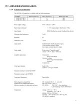
The SMT100-I-D amplifier is available with the following ratings: Power supply voltage 40 V < DC bus < 130 V Speed input command +/- 10 V analog input - Resolution: 10 bits. Speed signal BEMF feedback or encoder feedback (line driver). Minimum load inductance 1 mH Logic inputs Logic output Amplifier protections Front panel displays Enable/disable: Enable (negative logic) Limit switches (negative logic) Zero input command (positive logic) Relay contact "Amplifier ready" Power overvoltage No power voltage Power stage overtemperature Software I2t protection Fault LEDs Parameter setting via serial...
Open the catalog to page 5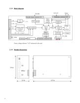
2.2.0 Block diagram +UP/-UP Encoder inputs connector X3 +5 V supply Motor voltage monitor Current monitor Analog input command sizing Speed loop Limit switches Encoder output AOK EEPROM Serial interface Current loop Protections processing Power voltage reference "-UP" referenced to the rack.
Open the catalog to page 6
2.4.0 Main protections Power stage overtemperature (fault is stored) In case of a power stage overheating (T > 90°C), the amplifier will disable the power stage. Overcurrent detection circuit (fault is stored) This circuitry will disable the amplifier as soon as the current exceeds the amplifier max. current (short-circuit at the motor phases). Power voltage monitoring Up DC Bus voltage should be between: 30 V < Up < 170 V : • Overvoltage for Up > 170 V +/-3 V (fault stored), • Undervoltage for Up < 30 V +/-3 V (fault stored). Possibility to disable this monitoring protection by making a jumper...
Open the catalog to page 7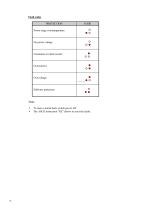
Fault codes • To reset a stored fault, switch power off . • The ASCII instruction "RZ" allows to reset the faults.
Open the catalog to page 8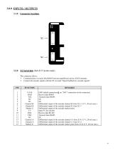
3.2.0 X2 Serial link (Sub-D 15 points male) This connector allows: • Communication via serial link RS485 between amplifier(s) and an ASCII terminal, • Connect the encoder signals with the NC in mode "Speed feedback by encoder signals".
Open the catalog to page 9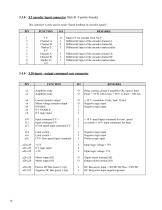
This connector is only used in mode "Speed feedback by encoder signals "
Open the catalog to page 10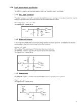
3.5.0 Logic inputs/outputs specification The SM-100/I amplifier has four logic inputs as well as an “amplifier ready” ouput signal. 3.5.1 Zero input command When the “zero input command” is activated, the amplifier receives a zero input command and immediatly stop the motor (except for the offset variation) whatever the speed input command value is. Positive logic input: 15 V < U < 24 V. The response time is about 500 µs. 100k 4.7k 3.5.2 Limit switch inputs If one of the limit switch contacts is activated during operation, the motor speed will be disabled in the direction corresponding to that...
Open the catalog to page 11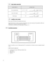
Relay contact AOK opens if any amplifier fault occurs. Note: On the 4 and 6 axes rack, two outputs corresponding to the serial connection of the amplifiers AOK relay contacts allow to process the information "rack failure". This function is described in the wiring diagram of chapter 6.1.4. Note: It is possible to use the “Addressing function” to communicate as a multiaxis system (see appendix chapter 9.1.0) ASCII Terminal Configuration • Communications speed: 4800 bauds (default value)
Open the catalog to page 12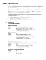
The SMT-100D amplifier is a digital amplifier. All command parameters are programmable via a serial link and can be saved in an EEPROM. The parameters are sent to the amplifier by an ASCII terminal. Each instruction is coded as 2 ASCII characters with or without parameter(s). These instructions allow to modify or read the value of a variable. When followed by a parameter, the variable corresponding to the instruction will take this value; otherwise, the amplifier will send back the current variable value via the serial link. Each instruction (possibly followed by a parameter) sent to the amplifier...
Open the catalog to page 13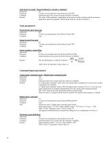
Scale factor in mode "Speed feedback by encoder resolution" Instruction Parameter Condition Remark SC Can have any hexadecimal value between 0 and FFFF. Instruction taken into account when the software is disabled. The value of this parameter is depending on the motor encoder resolution and the maximum application speed (see appendix "Speed signal mode by encoder resolution"). Gain parameters Proportional speed loop gain Instruction Parameter Condition KP Can have any hexadecimal value between 0 and 7FFF. none Integral speed loop gain Instruction Parameter Condition KI Can have any hexadecimal...
Open the catalog to page 14All Infranor Group catalogs and technical brochures
 XtrapulsPac_EN
4 Pages
 XtrapulsGemTemplates_e_1.4
21 Pages
 XtrapulsGem_User_Manual_v1.2.0.64
199 Pages
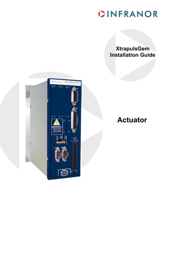 XtrapulsGem_Inst_e_2.1
42 Pages
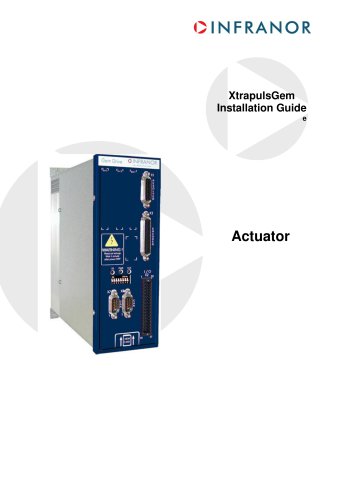 XtrapulsGem_Inst_e_2.0
42 Pages
 STO_declaration_Gem
2 Pages
 SMTBSi-2Tz_en_2.1
43 Pages
![SMT100D_e_1.01[1]](https://img.directindustry.com/pdf/repository_di/4620720/smt100d-e-101-1-1141223_1mg.jpg) SMT100D_e_1.01[1]
SMT100D_e_1.01[1]40 Pages
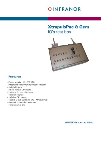 PacSimBox_e
1 Page
 PacSimBox_d_1
1 Page
 Pac-SF01_flyer_en_18.02
4 Pages
 Pac_User_1.2.1.218
253 Pages
 Pac_Templates_en_1.9
27 Pages
 Pac_STO_Installation_en_2.2
13 Pages
 Pac_SF01_operating_en_1.6
63 Pages
 Pac_SF01_EN
4 Pages
 Pac_Installation_en_2.23
82 Pages
 Pac_GDPS_CEconformity
1 Page
 Pac_flyer_en_17.12
4 Pages
 Pac_EC_conformity_25.04
1 Page
 Option_CT_EMF
6 Pages
 MOVINOR_LH055_LH086_LH097_LH142
23 Pages
 ma_series
6 Pages
 GemSafeTorqueOff_en_1.1
12 Pages
 GemProgramming_e_1.1
47 Pages
 GDPS_old_version_1.1_1
11 Pages
 CE_conformity_Gem
1 Page
 CD1pm_e_1.2(old)
18 Pages
 CD1pInst_e_7.2(old)
35 Pages
 CD1kInst_e_4.1(old)
40 Pages
 CD1k_CANopenProtocol_e_1.3(old)
86 Pages
 CD1a_e_7.1(old)
45 Pages
 Catalogue gamme SMT-BD1
11 Pages
 BM20A(F)v3_0
20 Pages
 BM20A(D)v3_0
20 Pages
 BF400(GB)v2_2
21 Pages
 BF400(D)v2_2
21 Pages
 BF230(GB)v2_0
23 Pages
 BF230(F)v2_0
23 Pages
 BD2m_e_2.2
69 Pages
 BD2m(GB)2.0
70 Pages
 BD2_e_3.2
53 Pages
 BD2(GB)3.1
53 Pages
 BD2(D)3.1
54 Pages
 Movinor_LH_e
4 Pages
 ma_series
6 Pages
 BD1t(GB)3.1
81 Pages
 BD1t(F)3.0
85 Pages
 BD1pInst(GB)3.0
25 Pages
 BD1pInst(F)3.0
23 Pages
 BD1pInst(D)3.0
24 Pages
 BD1pCD1pUse_e_2.4
57 Pages
 BD1m(GB)5.0
58 Pages
 BD1m(F)5.0
57 Pages
 BD1m(D)v3_3
64 Pages
 BD1k(GB)2.1
35 Pages
 BD1k(F)2.1
36 Pages
 BD1j(GB)v2_41
19 Pages
 BD1j(F)v2_4
21 Pages
 BD1i(GB)v2_21
23 Pages
 BD1i(F)v2_2
27 Pages
 BD1h(F)3.0
65 Pages
 BD1h(D)3.0
59 Pages
 BD1g(GB)v3_0
28 Pages
 BD1g(F)v3_0
28 Pages
 BD1f(GB)v2_01
18 Pages
 BD1f(F)v2_01
17 Pages
 BD1e(F)v2_01
22 Pages
 BD1d(GB)v2_01
25 Pages
 BD1d(F)v2_01
25 Pages
 BD1c(GB)v2_01
19 Pages
 BD1c(F)v2_01
19 Pages
 BD1a400(GB)v2_3
43 Pages
 BD1a400(F)v2_3
44 Pages
 BD1a400(D)v2_3
45 Pages
 BD1(GB)7.1_noPW
45 Pages
 BD1(GB)7.1
45 Pages
 BD1(F)7.1_noPW
47 Pages
 BD1(F)7.1
47 Pages
 BD1(D)7.1
45 Pages
 BD1 Katalog
11 Pages
 08ma_ms_e_01700
20 Pages
 Easy_User_5.0.1.60.2
190 Pages
 08ma_mrm_em_01575
20 Pages
 01ma_smv_e_01953
40 Pages
 PacHP-SF_Flyer_en_23.06
4 Pages
 IRD_User_Manual_en_1.2.XX.54.rev_b
216 Pages
 PacHP_User_en_1.2.8.100.b
280 Pages
 PacHP_TÜV_certificate_25.07
2 Pages
 PacHP_SF02_operating_en_1.6
103 Pages
 PacHP_SF01_operating_en_2.0
63 Pages
 PacHP_Installation_en_2.9
91 Pages
 PacHP_Series_Brochure
8 Pages
 PacHP_Flyer_us_20.10
4 Pages
 IRD_Installation_en_1.5
42 Pages
 IRD_EC_Conformity_25.03
1 Page
 GDPS_Installation_en_4.4
18 Pages
 EtherCAT Interface_en_1.3
20 Pages
 GDPS_EC_conformity_24.07
1 Page
 Easy_STO_en_1.4
14 Pages
 Easy_EC_Conformity_24_10
1 Page
 Easy_DB_STO_en_1.2
14 Pages
 Easy_DB_Installation_en_1.4
36 Pages
 CD1pmUser_en_4.2
55 Pages
 CD1pmInst_en_8.15
40 Pages
 CD1k_CANopenProtocol_en_2.10.1.1
108 Pages
 CD1pm_ProfibusProtocol_en_1.5
50 Pages
 CD1kUser_en_2.3
26 Pages
 CD1a_en_8.17
62 Pages
 CD1kInst_en_5.16
46 Pages
 CD1_STO_en_1.8
16 Pages
 CD1_STO_conformity_19.02
2 Pages
 CD1_flyer_en_14.09
4 Pages
 CD1_EC_conformity_24.05
1 Page
 Braking_Resistors_en_1.5
10 Pages
 AN_DC_bus_interfacing_en_1.3
5 Pages
 AN_CD1pm_SinCosTracks_e_1.0
7 Pages
 AN_CD1pm_AbsoluteEncoder_en_2.0
10 Pages
 AN_CD1ak_SinCosTracks_e_1.0
7 Pages
 AN_CD1ak_AbsoluteEncoder_en_2.0
10 Pages
 XtracontrolDC2_EN
4 Pages
 Flyer_VisiTouchCNC_EN_V1.1-1
2 Pages
 XtraforsWashdown_EN-2024
2 Pages
 DataSheet_CybIO_CNC_V1.0
6 Pages
 XtraforsPrime_EN-2024
2 Pages
 XtraforsMSS_EN
4 Pages
 XtraforsMSA_EN_2024
2 Pages
 XtraforsEx_EN-2024
2 Pages
 XtraforsBR_EN-2024
2 Pages
 XtraforsBL_EN-2024
2 Pages
 XtraforsBC-ed01-vs3
4 Pages
 Manual_XtraforsPrime
46 Pages
 Drawing_1
1 Page
 Datasheet_MSS
5 Pages
 Datasheet_2
2 Pages
 Datasheet_1
4 Pages
 BLSBLT_series
2 Pages
 BL220221
2 Pages
 BL270
BL2702 Pages
 BL190
BL1902 Pages
 bl100_series
6 Pages
 bl40_series
6 Pages
 BL30
BL302 Pages
 2019-01_XtraforsFP-DSL_FR
4 Pages
 Movinor_T_EN
4 Pages
 Movinor_N_EN
4 Pages
 Movinor_Low_Voltage_EN
4 Pages
 Manual Movinor T 03-2026
46 Pages
 Manual Movinor N 03-2026
63 Pages
 XtrapulsEasy™ AC servo-drive
4 Pages
 XtrapulsCD1 AC servo-drives
4 Pages
 CybIO
CybIO6 Pages
 AC SERVOMOTORS
2 Pages
 Movinor® N AC Servomotors
4 Pages