
- Catalogs
- Infranor Group
- PacHP_User_en_1.2.8.100.b


PacHP_User_en_1.2.8.100.b

PacHP_User_en_1.2.8.100.b
- Introduction and Architecture: Introduces the servo drives and outlines their architecture, referencing additional documents for installation and safety procedures.
- Commissioning: Details steps for software installation, drive communication, and parameter setting, including power supply configuration, motor configuration, and servo loop adjustments.
- Reference: Explains CanOpen communication, drive parameters, operation modes, and error management.
- Error Codes and Descriptions: Lists various error codes related to motor operations.
- I²t Protection: Describes the I²t function for motor protection.
- Braking Resistor Protection: Outlines the duty cycle limits for braking resistors.
- Stop Operation: Details various stop operations and their configurations.
- Drive Parameters: Covers drive power parameters, including peak and rated current.
- Motor Parameters: Lists motor parameters stored in object 0x6410.
- RMS Motor Current Calculation: Provides a formula for calculating RMS motor current.
- Braking Resistor Duty Cycle Limit: Provides a formula for calculating duty cycle limits.
- Stop Current Limit: Defines current limit for stop operations.
- Drive Voltage and Undervoltage Thresholds: Provides specific values for different drive operating voltages.
- Protection Mechanisms: Emphasizes the importance of protection mechanisms like I²t and braking resistor duty cycle limits.
- Stop Operations: Detailed stop operations and their configurations are crucial for ensuring safe and controlled motor shutdowns.
- Parameter Configurations: Accurate configuration of drive and motor parameters is essential for optimal performance and protection against faults.
- Catalog Date Code: Sub Index 4, Profinet PNU 0x6404, Unsigned16, rw access.
- Modification Date Code: Sub Index 5, Profinet PNU 0x6405, Unsigned16, rw access.
- Motor Type: Sub Index 6, Profinet PNU 0x6406, Unsigned16, rw access.
- Motor Max Speed: Sub Index 7, Profinet PNU 0x6407, Unsigned32, rw access, unit rpm.
- Motor Rated Speed: Sub Index 8, Profinet PNU 0x6408, Unsigned32, rw access, unit rpm.
- Motor Stall Current: Sub Index 9, Profinet PNU 0x6409, Unsigned32, rw access, unit mA.
- Motor Peak Current: Sub Index 10, Profinet PNU 0x640A, Unsigned32, rw access, unit mA.
- Torque Constant (Kt): Sub Index 11, Profinet PNU 0x640B, Unsigned16, rw access, unit 0.001Nm/A.
- Inertia: Sub Index 12, Profinet PNU 0x640C, Unsigned16, rw access, unit 0.001gm².
- Inductance: Sub Index 13, Profinet PNU 0x640D, Unsigned16, rw access, unit 0.1mH.
- Number of Motor Pole Pairs: Sub Index 14, Profinet PNU 0x640E, Unsigned16, rw access, value 1..24.
- Motor Phase: Sub Index 15, Profinet PNU 0x640F, Unsigned16, rw access, values 0x5555 or 0xAAAA.
- Motor Sensor Offset: Sub Index 16, Profinet PNU 0x6410, Unsigned16, rw access.
- Motor Temperature Probe: Sub Index 17, Profinet PNU 0x6411, Unsigned16, rw access.
- Motor Temperature Warning Threshold: Sub Index 18, Profinet PNU 0x6412, Unsigned16, rw access.
- Motor Temperature Error Threshold: Sub Index 19, Profinet PNU 0x6413, Unsigned16, rw access.
- Motor Pole Pitch: Sub Index 20, Profinet PNU 0x6414, Unsigned16, rw access.
- Auto-phasing Procedure: Initiated with signature 'apha'.
- Motor Phasing Procedure: Initiated with signature 'mcal'.
- Motor Control Parameters: Index 0x3410, includes number of motor pole pairs, motor phase, and motor offset.
- Activated by setting bit 12 of object 0x3442,0.
- Servo On/Off Timing Diagram: Defines motor brake and drive reaction times.
- Defines motor max and rated currents.
- Default configuration is 8kHz.
- q-Loop Proportional Gain (0x607C): Unsigned16, range 0-65535, read/write access.
- q-Loop Integral Gain (0x607D): Unsigned16, range 0-65535, read/write access.
- d-Loop Proportional Gain (0x607E): Unsigned16, range 0-65535, read/write access.
- d-Loop Integral Gain (0x607F): Unsigned16, range 0-65535, read/write access.
- Torque Offset (0x60B2): Integer16, unit per thousand of rated current, read/write access.
- Offset Torque Input Source (0x30B2): Unsigned32, connects 16-bit dataflow as target for Offset Torque.
- Torque Offset 2 (0x30B3): Integer16, similar to Torque Offset but without dynamic current limitation consideration.
- Torque Feedforward Command (0x30B4): Integer16, active only in "Operation Enable" state.
- Current Actual Value (0x6078): Integer16, provides DC current value in the drive.
- Dynamic Current Limits (0x30D1, 0x342B): Unsigned16, limits motor current dynamically.
- Dynamic Current Limit Configuration (0x30D2): Unsigned16, defines effect of Dynamic Current Limit signal.
- Motor Temperature Probe (0x3324): Configures motor temperature probe.
- IGBT Module Temperature (0x3328): Integer16, provides IGBT module temperature value.
- Position Feedback Sensor Select (0x306A): Unsigned16, defines feedback sensor for position loop.
- Motor Feedback Sensor Select (0x3070): Unsigned16, used for torque and speed control loops.
- Resolver Setup (0x3101): Configures resolver type, direction, and virtual marker Z settings.
- Resolver Calibration (0x3104, 0x3105): Procedures and parameters for resolver calibration.
- Index: 0x3109
- Data Type: Integer32
- Access: Read-only
- The resolver position is calculated as the sum of the internal position and an offset.
- Index: 0x3121
- Data Type: RECORD
- Number of Elements: 7
- Includes parameters for encoder type, configuration, virtual top Z shift and size, and zero mark pitch.
- Index: 0x3129
- Data Type: Integer32
- Access: Read-only
- The encoder position is the sum of the internal position and an offset.
- TTL Incremental Encoder
- Sin-Cos Incremental Encoder
- Hiperface Encoder
- Can be configured via PC software or manually.
- Includes both absolute and incremental information tracks.
- Auto-phasing is necessary for motor feedback.
- Position feedback requires setting the encoder resolution to match motor position scaling.
- Proportional Speed Gain (KPv): Enhances speed loop response.
- Integral Speed Gain (KIv): Improves axis stiffness.
- Integrator Low Frequency Limit (KIvf): Reduces motor heating.
- Damping Gain (KCv): Reduces speed loop overshoot.
- Derivative Speed Gain (KDv): Increases stability.
- Gain Scaling Factor (KJv): Adjusts all speed regulator gains.
- Current Command Filter: A 3rd order low-pass filter.
- Speed Measurement Filter: A 1st order low-pass filter.
- Proportional Position Gain (KPp): Enhances axis stiffness.
- Feedforward Speed Gains (KFp, KBv): Reduce following error.
- Feedforward Acceleration Gain (KAv): Reduces following error during acceleration.
- Current Loop Sampling Rate: Determined by PWM frequency.
- Position and Speed Loop Sampling Rate: Adjustable to influence servo loop stability.
- Speed Loop Monitoring: Includes parameters for speed set point, motor speed, speed loop error, and current command monitoring.
- Speed Following Error Threshold: Defines tolerance for speed error monitoring.
- Profile Position Mode (PP)
- Profile Velocity Mode (PV)
- Profile Torque Mode (PT)
- Homing Mode (HM)
- Interpolated Position Mode (IP)
- Cyclic Synchronous Position Mode (CSP)
- Cyclic Synchronous Velocity Mode (CSV)
- Cyclic Synchronous Torque Mode (CST)
- Analog Speed Mode (AS) - Not supported by EtherCAT
- Stepper Emulation Mode (SE) - Not supported by EtherCAT
- Sequence Mode (SQ)
- Reserved
- Analog Torque Mode (AT)
- Master-Slave Gearbox Mode (GB) - Not supported by EtherCAT
- Master-Slave Cam Mode (CM) - Only for PPAC-22 customization
- Target Position (0x607A): Defines the final motor position.
- Max Motor Speed (0x6080): Sets the maximum speed.
- Profile Velocity (0x6081): Running velocity for positioning.
- End Velocity (0x6082): Final velocity at target position.
- Profile Acceleration (0x6083) and Deceleration (0x6084): Define acceleration and deceleration rates.
- Motion Profile Type (0x6086): Determines profile type.
- Position Window (0x6067) and Time (0x6068): Define acceptable position range and time.
- Max Profile Velocity (0x607F): Limits maximum speed during profiled moves.
- Index: 0x6079
- Data Type: Integer32
- Access: Read-only
- Unit: mV
- Description: Provides the DC voltage value in the drive.
- Objects include target position, velocity, and torque offsets.
- Focuses on target velocity and torque offset.
- Target Torque is the setpoint for motor current.
- Allows basic moves called sequences.
- Main parameters: position, speed, acceleration, deceleration, and delay time.
- Parameters include home offset, method, speeds, acceleration, and current limit.
- Parameters: speed setpoint, acceleration, deceleration, and running time.
- Parameters: speed setpoint, acceleration, running time, and current limit.
- Sequence Link (PNU 0x3613): Integer16, rw access.
- Output Trigger (PNU 0x3614): Unsigned16, rw access.
- Output Bits (PNU 0x3615-0x3618): Unsigned16, rw access.
- Position and Speed Parameters (PNU 0x361C-0x361F): Integer32, rw access.
- Acceleration and Deceleration (PNU 0x3620-0x3621): Unsigned32, rw access.
- Configuration (PNU 0x3624): Unsigned16, rw access.
- Gearbox Ratio Parameters (Index 0x3921): Allows setting numerator and denominator for two gearing ratios.
- Gearbox Distances Parameter (Index 0x3925): Defines master, slave, and synchronization distances.
- Gearbox Configuration/Factor (Index 0x3928): Configures gearbox behavior.
- Data Type: Unsigned16
- Access: Read/Write
- This parameter defines a ratio factor applied to the master-slave ratio.
- Index: 0x60FD
- Data Type: Unsigned32
- Access: Read/Write
- Index: 0x60FE
- Data Type: Unsigned32
- Access: Read/Write
- Digital Inputs Polarity: Configured using index 0x3051.
- Digital Outputs: Managed through index 0x60FE.
- Digital Outputs Polarity: Set via index 0x3055.
- Digital User Inputs/Outputs: Includes 16-bit inputs and outputs, configured at 0x3058.
- Analog Input 1: Configured with index 0x30F1.
- Analog Input 2: Managed through index 0x30F2.
- Analog Output 1: Configured using index 0x30A1.
- Digital Cam Positions: Configured with index 0x30E0.
- Digital Cam Configuration: Managed through index 0x30E1.
- Oscillo Function Support: Configured at index 0x5800.
- Oscillo Buffer Configuration: Managed through index 0x5804.
- Oscillo Trigger Configuration: Includes trigger control and status, configured at index 0x5820.
- Oscillo Buffer Transfer: Managed through index 0x5840.
Catalog excerpts
User Guide DIGITAL SERVO DRIVES FOR BRUSHLESS AC MOTORS
Open the catalog to page 1
XtrapulsPacHP – User Guide ! This is a general manual describing a series of servo drives having output capability suitable for driving AC brushless sinusoidal servo motors. Please see also: o XtrapulsPacHP Installation Guide for the hardware installation of the drive (mounting, wiring, …). o XtrapulsPacHP SF01 Safety version operating manual o XtrapulsPacHP SF02 Safety version operating manual o EtherCAT fieldbus interface manual for the XtrapulsPacHP-et or ed version o PROFINET fieldbus interface manual for the XtrapulsPacHP-pn version o XtrapulsGDPS manual, for the use of the XtrapulsGDPS...
Open the catalog to page 2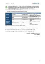
XtrapulsPacHP - User Guide CINFRANOR In accordance with the Decree nr. 2012-617 of May 2nd, 2012 which specifies the provisions related to the professional EEE manufacturers' obligations, INFRANOR France is a member of RECYLUM: ecoorganization ecosystem certified for the collection, treatment and recycling of WEEE. In France, RECYLUM allows all professionals benefiting from a free collection and recycling solution, in observance of the regulation, the environment and health. Information and sorting instructions regarding INFRANOR products Sorting instructions may vary according to regions / countries....
Open the catalog to page 3
XtrapulsPacHP – User Guide
Open the catalog to page 4
XtrapulsPacHP - User Guide
Open the catalog to page 5
XtrapulsPacHP – User Guide Chapter 1 - General Description 1.1 - INTRODUCTION The XtrapulsPacHP drive directly controls the motor torque and speed from of the information provided by a high resolution position sensor (resolver or encoder). The sinusoidal current commutation generated from the information of this high resolution position sensor ensures very smooth motor torque/force control. The XtrapulsPacHP drive can be configured for the feedback of various position sensor types. The appropriate position sensor configuration is selectable by software and saved in the drive. ▪ With a resolver...
Open the catalog to page 6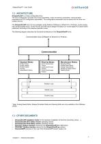
XtrapulsPacHP - User Guide 1.2 - ARCHITECTURE XtrapulsPacHP is a freely configurable drive. The drive configuration includes servo-loop parameters, motor and sensor parameters, communication parameters and I/O configuration parameters. The configuration parameters can be stored into the drive nonvolatile memory. The XtrapulsPacHP drive can be controlled via the fieldbus (CANopen or EtherCAT or Profinet), via the analog input (analog speed drive), via the PULSE and DIR inputs (stepper emulation) or via the digital I/Os (stand-alone positioner) according to the selected operation mode. The following...
Open the catalog to page 7
XtrapulsPacHP - User Guide This chapter describes the commissioning procedure of the drive by means of the Optio software. / • \ Do not perform the drive parameterization by means of both Optio software tool and ^ ™ CANopen bus at the same time. The Optio Drive Assistant software is PC compliant under Windows and allows an easy parameterization of the XtrapulsPacHP drive range. Please see our website www.infranor.com for downloading the Optio software. Minimum Configuration The use of the Optio Drive Assistant software requires the minimum PC configuration described below: • 15" screen, 256 color...
Open the catalog to page 8
XtrapulsPacHP - User Guide CINFRANOR2.2 - STARTING THE SOFTWAREProject management The Optio software allows the parameterization of all Xtrapuls drives for a given application. All Xtrapuls drives of a given application, connected together via CANopen, can be included in the same project. Each Xtrapuls drive of the project is identified by its node ID. The Xtrapuls drive node ID code values must all be different from each other in the same project. The different software commands allow: - Opening an existing project, - Adding and/or removing axes in the project, Each parameter (object) of the...
Open the catalog to page 9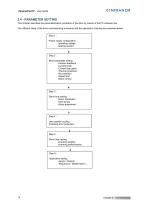
XtrapulsPacHP – User Guide 2.4 - PARAMETER SETTING This chapter describes the parameterization procedure of the drive by means of the PC software tool. The different steps of the drive commissioning procedure and the operations chaining are presented below. Step 1 : Power supply configuration -operating voltage -braking resistor Step 2 : Motor parameter setting -Position feedback -Current limits -Current loop gains -Thermal protection -I2t protection -Speed limit -Motor control Step 3 : Servo loop setting -Gains calculation -Auto-tuning -Gains adjustment Step 4 : User position scaling Following...
Open the catalog to page 10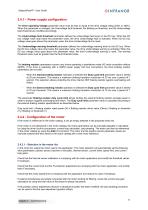
XtrapulsPacHP - User Guide 2.4.1 – Power supply configuration The Drive operating Voltage parameter value must be less or equal to the drive voltage rating (230V or 400V). When this parameter is changed, the Overvoltage fault threshold, the Braking on threshold, and the Undervoltage fault threshold are modified accordingly. The Undervoltage fault threshold parameter defines the undervoltage fault level on the DC bus. When the DC bus voltage value drop below this parameter value, the drive Undervoltage fault is activated. When the DC bus voltage value goes above this parameter value, the drive...
Open the catalog to page 11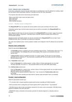
XtrapulsPacHP - User Guide If the motor configuration must be manually made (motor is not referenced in the PC software tool catalog), adjust first the position sensor parameters (resolver or encoder) and then the motor parameters. The required motor data for the manual setup are listed below: - Motor current limits: rated current and peak current - Motor speed limit - Motor pole pairs - Motor winding inductance The XtrapulsPacHP drive can operate with various position sensor type according to the drive version. Transmitter resolver type or SinCos tracks resolver type can both be connected to...
Open the catalog to page 12
XtrapulsPacHP - User Guide Incremental encoder setting: Enter the Resolution parameter value according to the encoder mounting and the mechanical ratio for a given application. For a rotating motor, Resolution refer to one motor shaft revolution. For a linear motor, Resolution refer to one motor pole pitch (N to N or S to S magnets distance). Enter the Zero Mark pitch parameter value if the encoder has got a Zero-mark channel. Zero Mark pitch refer to the distance between 2 successive zero-mark signals (generally one encoder shaft revolution for a rotating encoder). If the encoder is not equipped...
Open the catalog to page 13All Infranor Group catalogs and technical brochures
 XtrapulsPac_EN
4 Pages
 SMTBSi-2Tz_en_2.1
43 Pages
 PacSimBox_d_1
1 Page
 Pac-SF01_flyer_en_18.02
4 Pages
 Pac_User_1.2.1.218
253 Pages
 Pac_Templates_en_1.9
27 Pages
 Pac_STO_Installation_en_2.2
13 Pages
 Pac_SF01_operating_en_1.6
63 Pages
 Pac_SF01_EN
4 Pages
 Pac_Installation_en_2.23
82 Pages
 Pac_flyer_en_17.12
4 Pages
 Option_CT_EMF
6 Pages
 MOVINOR_LH055_LH086_LH097_LH142
23 Pages
 ma_series
6 Pages
 GemSafeTorqueOff_en_1.1
12 Pages
 CD1pm_e_1.2(old)
18 Pages
 CD1pInst_e_7.2(old)
35 Pages
 CD1kInst_e_4.1(old)
40 Pages
 CD1k_CANopenProtocol_e_1.3(old)
86 Pages
 CD1a_e_7.1(old)
45 Pages
 Catalogue gamme SMT-BD1
11 Pages
 BM20A(F)v3_0
20 Pages
 BM20A(D)v3_0
20 Pages
 BF400(GB)v2_2
21 Pages
 BF400(D)v2_2
21 Pages
 BF230(GB)v2_0
23 Pages
 BF230(F)v2_0
23 Pages
 BD2m_e_2.2
69 Pages
 BD2m(GB)2.0
70 Pages
 BD2_e_3.2
53 Pages
 BD2(GB)3.1
53 Pages
 BD2(D)3.1
54 Pages
 Movinor_LH_e
4 Pages
 ma_series
6 Pages
 BD1t(GB)3.1
81 Pages
 BD1t(F)3.0
85 Pages
 BD1pInst(GB)3.0
25 Pages
 BD1pInst(F)3.0
23 Pages
 BD1pInst(D)3.0
24 Pages
 BD1pCD1pUse_e_2.4
57 Pages
 BD1m(GB)5.0
58 Pages
 BD1m(F)5.0
57 Pages
 BD1m(D)v3_3
64 Pages
 BD1k(GB)2.1
35 Pages
 BD1k(F)2.1
36 Pages
 BD1j(GB)v2_41
19 Pages
 BD1j(F)v2_4
21 Pages
 BD1i(GB)v2_21
23 Pages
 BD1i(F)v2_2
27 Pages
 BD1h(F)3.0
65 Pages
 BD1h(D)3.0
59 Pages
 BD1g(GB)v3_0
28 Pages
 BD1g(F)v3_0
28 Pages
 BD1a400(GB)v2_3
43 Pages
 BD1a400(F)v2_3
44 Pages
 BD1a400(D)v2_3
45 Pages
 BD1(GB)7.1_noPW
45 Pages
 BD1(GB)7.1
45 Pages
 BD1(F)7.1_noPW
47 Pages
 BD1(F)7.1
47 Pages
 BD1(D)7.1
45 Pages
 BD1 Katalog
11 Pages
 Easy_User_5.0.1.60.2
190 Pages
 01ma_smv_e_01953
40 Pages
 PacHP-SF_Flyer_en_23.06
4 Pages
 IRD_User_Manual_en_1.2.XX.54.rev_b
216 Pages
 PacHP_SF02_operating_en_1.6
103 Pages
 PacHP_SF01_operating_en_2.0
63 Pages
 PacHP_Installation_en_2.9
91 Pages
 PacHP_Series_Brochure
8 Pages
 PacHP_Flyer_us_20.10
4 Pages
 IRD_Installation_en_1.5
42 Pages
 Easy_STO_en_1.4
14 Pages
 Easy_DB_STO_en_1.2
14 Pages
 Easy_DB_Installation_en_1.4
36 Pages
 CD1pmUser_en_4.2
55 Pages
 CD1pmInst_en_8.15
40 Pages
 CD1k_CANopenProtocol_en_2.10.1.1
108 Pages
 CD1pm_ProfibusProtocol_en_1.5
50 Pages
 CD1kUser_en_2.3
26 Pages
 CD1a_en_8.17
62 Pages
 CD1kInst_en_5.16
46 Pages
 CD1_STO_en_1.8
16 Pages
 CD1_flyer_en_14.09
4 Pages
 Braking_Resistors_en_1.5
10 Pages
 XtracontrolDC2_EN
4 Pages
 Flyer_VisiTouchCNC_EN_V1.1-1
2 Pages
 XtraforsWashdown_EN-2024
2 Pages
 DataSheet_CybIO_CNC_V1.0
6 Pages
 XtraforsPrime_EN-2024
2 Pages
 XtraforsMSS_EN
4 Pages
 XtraforsMSA_EN_2024
2 Pages
 XtraforsEx_EN-2024
2 Pages
 XtraforsBR_EN-2024
2 Pages
 XtraforsBL_EN-2024
2 Pages
 XtraforsBC-ed01-vs3
4 Pages
 Manual_XtraforsPrime
46 Pages
 Drawing_1
1 Page
 Datasheet_MSS
5 Pages
 Datasheet_2
2 Pages
 Datasheet_1
4 Pages
 BLSBLT_series
2 Pages
 BL220221
2 Pages
 BL270
BL2702 Pages
 BL190
BL1902 Pages
 bl100_series
6 Pages
 bl40_series
6 Pages
 BL30
BL302 Pages
 2019-01_XtraforsFP-DSL_FR
4 Pages
 Movinor_T_EN
4 Pages
 Movinor_N_EN
4 Pages
 Movinor_Low_Voltage_EN
4 Pages
 Manual Movinor T 03-2026
46 Pages
 Manual Movinor N 03-2026
63 Pages
 XtrapulsEasy™ AC servo-drive
4 Pages
 XtrapulsCD1 AC servo-drives
4 Pages
 CybIO
CybIO6 Pages
 AC SERVOMOTORS
2 Pages
 Movinor® N AC Servomotors
4 Pages






Archived catalogs
 AN_CD1ak_AbsoluteEncoder_en_2.0
10 Pages
 AN_CD1ak_SinCosTracks_e_1.0
7 Pages
 AN_CD1pm_AbsoluteEncoder_en_2.0
10 Pages
 AN_CD1pm_SinCosTracks_e_1.0
7 Pages
 AN_DC_bus_interfacing_en_1.3
5 Pages
 CD1_EC_conformity_24.05
1 Page
 CD1_STO_conformity_19.02
2 Pages
 EtherCAT Interface_en_1.3
20 Pages
 Easy_EC_Conformity_24_10
1 Page
 GDPS_EC_conformity_24.07
1 Page
 IRD_EC_Conformity_25.03
1 Page
 PacHP_TÜV_certificate_25.07
2 Pages
 BD1c(F)v2_01
19 Pages
 BD1c(GB)v2_01
19 Pages
 BD1d(F)v2_01
25 Pages
 BD1d(GB)v2_01
25 Pages
 BD1e(F)v2_01
22 Pages
 BD1f(F)v2_01
17 Pages
 BD1f(GB)v2_01
18 Pages
 Pac_EC_conformity_25.04
1 Page




















